


Alternator Field/ VR (Voltage Reference)
• Theory of Operation
A voltage regulator (in the PCM) controls alternator output by adjusting the amount of current flowing through the
rotor field windings. To increase alternator output, the voltage regulator allows more current to flow through the rotor
field windings. The field control current is varied according to the battery’s need for charge and ambient temperature.
If the battery is discharged, the regulator may cycle the field current on 90 % of the time to increase the alternator
output. If the electrical load is low, the regulator may cycle the field current off 90 % of the time to decrease the
alternator output. That is the signal is usually pulse width modulated.
If the field con
t
rol circuit is malfunctioning
,
the charging sys
t
em can overcharge or undercharge, either creating
problems.
• Symptoms
Undercharging, overcharging, or no charging output
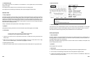
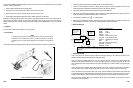
• Test Procedure
1.
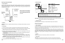
Connect the CH A lead to the field control circuit the and its ground lead to the chassis GND.
2. Start the engine and run at 2500 RPM. Operate the heater fan on high with the headlight on high beam, or use
battery load tester to vary the amount of load on the vehicle’s electrical system.
3. Make sure that the voltage regulator is properly controlling the duty cycle of the alternator field drive signal as the
load changes.
• Reference Waveform
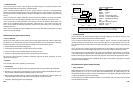
VEHICLE INFORMATIONS
YEAR
:
1986
MAKE : Oldsmobile
MODEL : Toronado
ENGINE : 3.8 L
FUELSYS : Multiport Fuel Injection
PCM_PIN : 3D11 at BCM Grey wire at alternator pin F
RPM
:
2500
ENG_TMP : Operating Temperature
VACUUM
: 18 In. Hg
MILEAGE : 123686
6-53
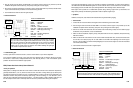
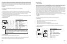
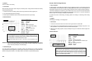
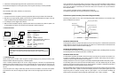
The charging system’s voltage regulator should vary
the on-
t
ime of
the alternator’s
field control driv e signal depending on the electrical sys
t
em requirements. The
regulator should pulse the field drive signal with the overall duty cycle average meeting
the electrical system demands. When electrical load is pu
t
on the battery, the
field
control circuit should go high to compensate for it. Frequency
may increase during
conditions of increased charging demand.
FREQ = 390 Hz
DUTY = 21.8 %
NOTE: A/C on high blow and headlights on
highbeam.
• Symptoms
No start, low battery, slow cranking
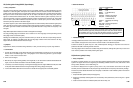
• Test Procedure
Before performing the alternator output voltage test, the battery’s state of charge should be checked and a battery
load test should be performed.
1. Connect the CH A lead to the battery positive post and its ground lead to the battery negative post.
2. Turn off all electrical loads and start the engine.
3. Hold the engine at 2500 RPM for about 3 minutes and check the alternator’s output voltage.
• Reference Waveform
VEHICLE INFORMATIONS
YEAR
:
1986
MAKE : Oldsmobile
MODEL : Toronado
ENGINE : 3.8 L
FUELSYS : Multiport Fuel Injection
PCM_PIN : CH A to Positive side of Battery
COM to GND
STATUS : KOER (Key On Running)
RPM : 2500
ENG_TMP
:
Operating Temperature
VACUUM :
20 In. Hg
MILEAGE : 123686
IMPORTANT :
The test results can be different in a big way according to the ambient temperature, what electrical
loads are on the battery during testing, the age of battery, the battery’s charging state, the level and
quality of the battery’s electrolyte, or the battery design.
• Troubleshooting Tips
If the output voltage is excessively high, or the battery is leaking, wet, smells like acid, or is boiling, the alternator
may be defective. Check the regulator for its proper operation. Also perform a voltage drop test on both sides of the
alternator housing and at the battery. If the voltage is different, the alternator may be grounded improperly.
6-52
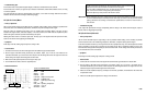
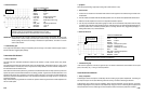
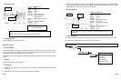
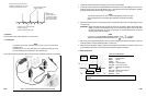
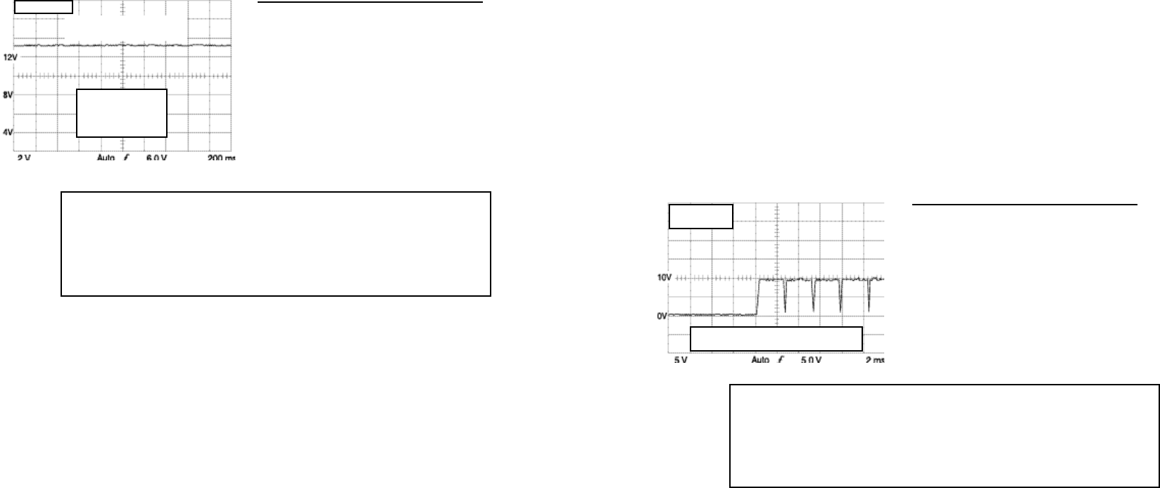
Normal voltage ranges are about 0.8 V to 2.0 V above the static battery voltage with
the Key Off Engine Off. Over 2.0 V may indicate an overcharge condition and less than
0.8 V may indicate an undercharge solution. Different vehicles have different charging
system specifications. Consult the manufacturer’s specs.
General rules of thumb; GN 14.5 to 15.4 V, Ford 14.4 to 14.8 V, and Chrysler 13.3 to
13.9 V
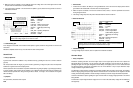
AVG = 13.2 V
Normal voltage ranges
are from 0.8 volts to 2.0
volts above engine off
(static) battery voltage.
Test conducted with engine
running and A/C off.