


3. Exercise the sensor, device, or circuit while watching for the amplitude of the signal. The amplitude should stay in
a predetermined voltage range for a given condition.
4. In most cases, the amplitude of the waveform should stay at the battery voltage when the circuit is on, and go to
0 V when the circuit is off.
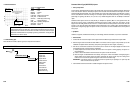
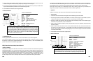
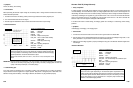
• Reference Waveform
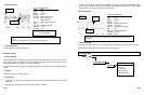
VEHICLE INFORMATIONS
YEAR
:
1986
MAKE : Oldsmobile
MODEL : Toronado
ENGINE : 3.8 L
FUELSYS : Multiport Fuel Injection
PCM_PIN :
C16 Org and D1 BlkWht wires
STATUS : KOER (Key On Running)
RPM : Idle
ENG_TMP : Operating Temperature
VACUUM
:
20 In. Hg
MILEAGE : 123686
• Troubleshooting Tips
I
f
the amplitude is changing
when it is not supposed to (for example, when
the switch in the
circui
t
is not being
operated), there may be a failure in the circuit.
If
t
he waveform has some spikes
to ground, there may be an open circuit in the power side or there may be a
voltage short to ground.
If the waveform has some upward spikes, there may be an open circuit in the ground side.
Voltage Reference (V Ref) Circuit
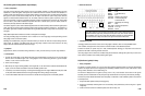
• Theory of Operation
The PCM provides a stable regulated voltage, normally 5 V DC (8 V or 9 V DC on some older vehicles), to sensors
and components controlled by it for operation. The V Ref circuit should stay at their specified voltage during normal
operation. (The voltage level should not vary more than 200 mV under normal operation.)
• Symptoms
Low power, sensor output values out of range
• Test Procedure
1. Connect the CH A lead to the V Ref signal from the PCM and its ground lead to the sensor or chassis GND.
6-49
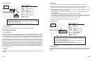
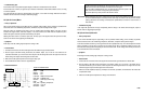
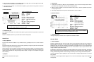
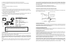
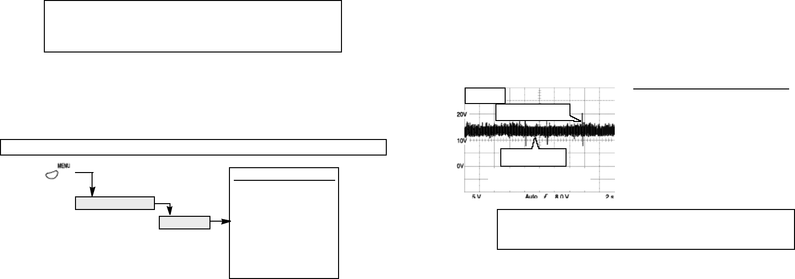
MAX = 20.3 V
MIN = 8.00 V
transient spikes are normal
with engine running
scope connected to
PCM power and ground
wiggle or shake wiring harness or
wires to suspect component while
looking for drop outs in the waveform
The voltage should stay in a predetermined voltage range for a given condition (during
normal opera
t
ion)
.
Transien
t
spikes
above average voltage level are normal with
engine running.
• Troubleshooting Tips
If the waveform stays flat (at 0 V), suspect a faulty glow plug. If the waveform has drop outs, suspect an open circuit
in the glow plug’s heating element. An open circuit may be caused by overheat from a faulty controller, vibration, or
fatigue related malfunctions.
6.4 ELECTRICAL TESTS
Power Supply Circuit
• Theory of Operation
This test procedure tests the integrity of the battery power supply to vehicle as well as to subsystems or switches
tha
t
rely on bat
t
ery power to operate. This
test procedure can be used
t
o assure components and devices are
getting the quality and quantity of power supply necessary for proper operation. This procedure can be applied to a
lot of different automotive circuits that use battery voltage as their power source, such as power supply circuits (to
PCM and other control modules), temperature switches, throttle switches, vacuum switches, light switches, brake
switches, cruise control switches, etc.
• Symptoms
No start, loss of power
• Test Procedure
1. Connect the CH A lead to the power supply circuit of the device to be tested and its ground lead to the device’s
GND.
2. Make sure power is switched on in the circuit so that the sensor, device or circuit is operational and current is
flowing through the circuit.
6-48
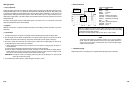
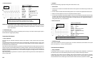
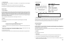
Look for the curren
t
going
through the glow plug to be at
its maximum when the
ignition key is switched on. Maximum current and operating current specifications may
be available from the manufacturer’s service manual.
All glow plugs should draw about the same current under cold or hot conditions.
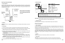
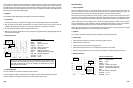
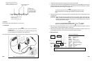
ELECTRICAL
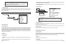
COMPONENT TESTS
ELECTRICAL TESTS MENU
Power Circuit
V Ref Circuit
Ground Circuit
Alternator Output
Alternator Field VR
Alternator Diode
Audio System
DC Switch Circuits
MENU ( )