


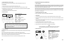
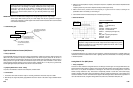
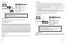
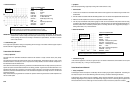
Saturated Switch Type (MFI/PFI/SFI) Injector
•
Theory of Operation
The fuel injector itself determines the height of the release spike. The injector driver (switching transistor) determines
most of the waveform features. Generally an injector driver is located in the PCM that turns the injector on and off.
Different Kinds (Saturated Switch type, Peak-and-Hold type, Bosch type Peak-and-Hold, and PNP
type) of injector
drivers create different waveforms. Knowing how to interpret injector waveforms (determining on-time, referencing
peak height,
recognizing bad drivers, etc.) can be a very valuable diagnostic talent for driveabili
t
y
and emission
repair.
Saturated switch injector drivers are used primarily on
multiport fuel
injection (MF
I
, PFI, SFI)
systems where the
injectors are fired in groups or sequentially. Determining the
injector on-
t
ime is fairly easy. The injector
on-time
begins where the PCM grounds the circuit to turn it on and ends where the PCM opens the control circuit. Since the
injector is a coil, when its electric field collapses from the PCM turning it off, it creates a spike. Saturated Switch type
injectors have a single rising edge. The injector on-time can be used to see if the Feedback Fuel Control System is
doing its job.
• Symptoms
Hesitation, rough idle, intermittent stall at idle, poor fuel mileage, emissions test failure, low power on acceleration
• Test Procedure
1. Connect the CH A lead to the injector control signal from the PCM and its ground lead to the injector GND.
2.
S
tar
t
the
engine
and
hold throt
t
le at 2500 RPM
f
or
2-3 minutes until the
engine is
f
ully warmed up and the
Feedback Fuel System enters closed loop. (Verify this by viewing the O
2
sensor signal, if necessary.)
3. Shut off A/C and all other accessories. Put vehicle in park or neutral. Rev the engine slightly and watch for the
corresponding injector on-time increase on acceleration.
1) Induce propane into the intake and drive the mixture rich. If the system is working properly, the injector on-
time will decrease.
2) Create a vacuum leak and drive the mixture lean. The injector on-time will increase.
3) Raise the engine to 2500 RPM and hold it steady. The injector on-time will modulate from slightly larger to
slightly smaller as the system controls the mixture. Generally, the injector on-time only has to change from
0.25 ms to 0.5 ms to drive the system through its normal full rich to full lean range.
IMPORTANT: If the injector on-time is not changing, either the system may be operating in an “open loop” idle
mode or the O
2
sensor may be bad.
4. Use the Glitch Snare mode to check for sudden changes in the injector on-time.
6-33
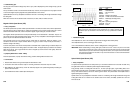
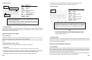
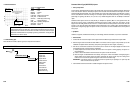
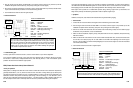
• Reference Waveform
VEHICLE INFORMATIONS
YEAR
:
1994
MAKE : Ford
MODEL : Explorer
ENGINE : 4.0 L
FUELSYS :
Multiport Fuel Injection
PCM_PIN : 27 BrnLtGrn wire
STATUS : KOER (Key On Running)
RPM : Snap Acceleration
ENG_TMP : Operating Temperature
VACUUM : 3-24 In. Hg
MILEAGE : 40045
• Troubleshooting Tips
There should be no breaks, spikes to ground, or dropouts in the waveform.
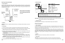
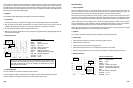
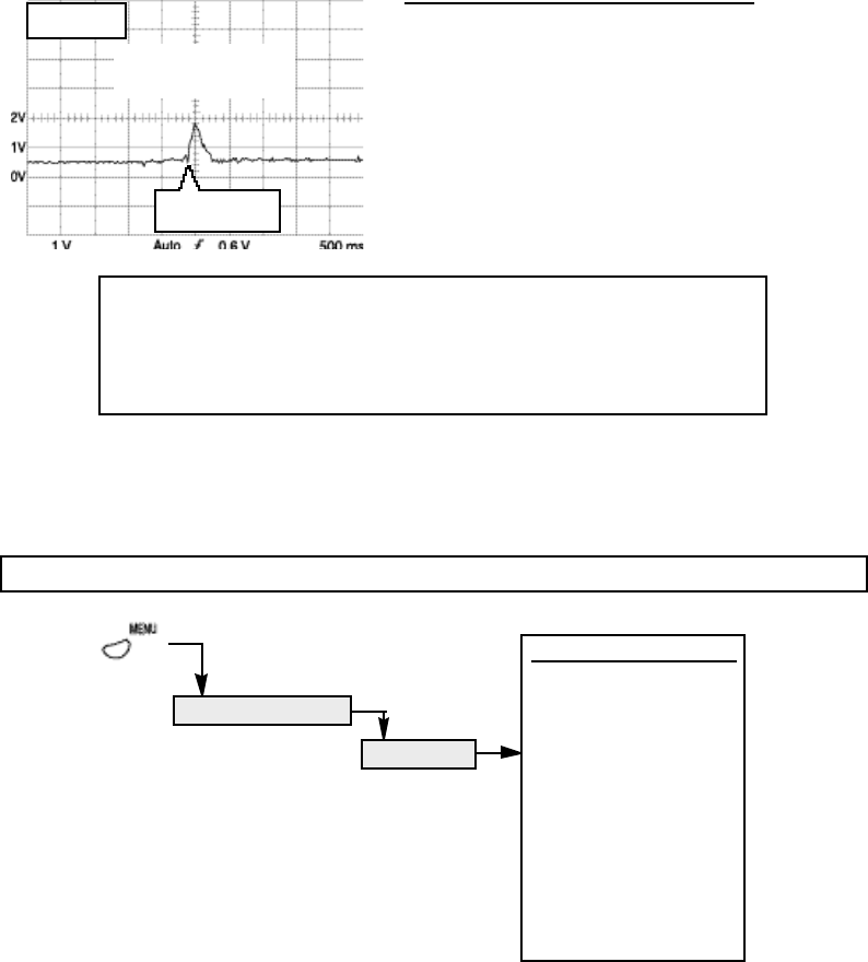
6.3 ACTUATOR TESTS
6-32
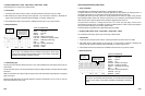
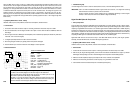
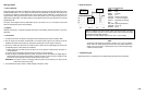
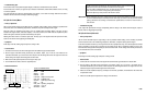
As soon as the engine reaches the predetermined
EGR requirement conditions, the
PCM will begin opening the EGR valve. The waveform should rise when the engine is
accelerated. The waveform
should fall when
the EGR valve closes and the
engine
decelerates. EGR demands are especially high during accelerations. During idle and
deceleration, the valve is closed.
MAX = 1.86 V
MIN = 400 mV
Ford EGR Differential Pressure
Sensor logged during snap
acceleration
Engine accelerated
here
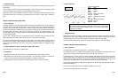
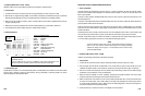
ACTUATORS
COMPONENT TESTS
ACTUATOR TESTS MENU
Injector PFI/MFI
Injector TBI
Injector PNP
Injector Bosch
Mixture Cntl Sol
EGR Cntl Sol
IAC Motor
IAC Solenoid
Trans Shift Sol
Turbo Boost Sol
Diesel Glow Plug
MENU ( )