


• Troubleshooting Tips
If overall voltage is low, be sure to check for cracked, broken, loose, or otherwise leaking intake air ducts.
IMPORTANT:
0.25 V can make the difference between a good sensor and a bad one, or an engine that is blowing
black smoke and one that is in perfect control of fuel mixture.
However, because the sensor output voltages will vary substantially depending
on vehicle engine
families, in some cases, this sensor can be difficult to diagnose definitively.
Digital Slow MAF (Mass Air Flow) Sensor
•
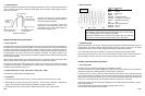
Theory of Operation
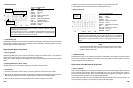
There are three main varieties of digital MAF sensors; Digital Slow type (output signals in the 30 to 500 Hz range),
Digital Fast type (output signals in the kHz range), and Karman Vortex type (which changes pulse width as well as
frequency). A digital MAF sensor receives a 5 V reference signal from the PCM and sends back a variable frequency
signal that is proportional to the mass of air entering the engine. The output signal is a square wave, in most cases,
with a full 5 V in amplitude. As the airflow increases, the frequency of the signal generated increases. The PCM uses
these signals to calculate fuel injector ON time and ignition timing and also determines MAF sensor deterioration by
comparing the MAF signal to a calculated value based on MAP, TP, IAT, and RPM signals.
Digital
S
low MAF sensors can be
f
ound on early to mid 1980’s GM vehicles, and many other engine
systems.
Generally, the older the MAF sensor, the slower the frequency it produces.
• Symptoms [OBD II DTC’s: P0100 ~ P0104]
Hesitation, stall, low power, idle problems, excessive fuel consumption, emissions failure
• Test Procedure
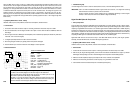
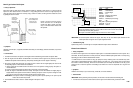
1. Connect the CH A lead to the sensor output or HI and its ground lead to the sensor output LO or GND.
2. With the Key On, Engine Running (KOER), use the throttle to accelerate and decelerate the engine. Try different
RPM ranges while spending more time in the RPM ranges that correspond to the driveability problem.
3. Make sure that the amplitude, frequency and shape are all correct, consistent, and repeatable.
4.
Make sure that the sensor generates the correct frequency for a given RPM or airflow rate.
5. Use the Glitch Snare mode to detect dropouts or unstable output frequency.
6-27
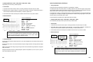
Vane type MAF sensors, mainly, consist of a variable resistor (potentiometer) that tells the PCM the position of the
vane air flow door. As the engine is accelerated and more air passes through the vane air flow sensor, the vane air
door is pushed open by the incoming air. The angle of the vane air flow door is proportional to the volume of air
passing by it. A vane type MAF sensor consists of a contact connected to the vane door which slides over a section
of resistance material that is places around the pivot axis for the movable contact. The voltage at any point in the
resistance material, as sensed through the movable contact
,
is proportional to
t
he angle of
the vane air door.
Overswing of the door caused by snap accelerations provides information to the PCM for acceleration enrichment.
[Many Toyotas are equipped with vane type MAF sensors operating opposite the above – their voltage is high when
airflow is low.]
• Symptoms [OBD II DTC’s: P0100 ~ P0104]
Hesitation, stall, low power, idle problems, excessive fuel consumption, emissions failure
• Test Procedure
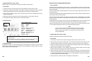
1.
Connect the CH A lead to the sensor output or HI and its ground lead to the sensor output LO or GND.
2. Shut off all accessories, start the engine and let it idle in park or neutral. After the idle has stabilized, check the
idle voltage.
3. Rev the engine from idle to Wide Open Throttle (WOT) with a moderate input speed (this should only take about
2 seconds – don’t overrev the engine).
4. Let engine speed drop back down to idle for about two seconds.
5. Rev the engine again to WOT (very quickly) and let it drop back to idle again.
6. Press the HOLD key to freeze the waveform on the display for closer inspection.
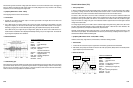
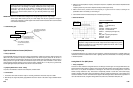
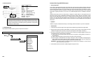
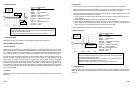
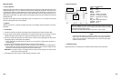
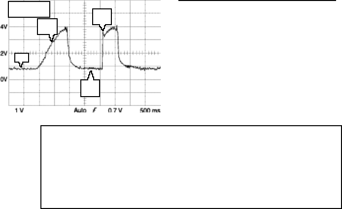
• Reference Waveform
VEHICLE INFORMATIONS
YEAR
:
1993
MAKE : Ford
MODEL : Explorer
ENGINE : 4.0 L
FUELSYS :
Multiport Fuel Injection
PCM_PIN : 14 LtBlu Red wire
STATUS :
KOER (Key On Running)
RPM : Acceleration and Deceleration
ENG_TMP : Operating Temperature
VACUUM : 2-24 In. Hg
MILEAGE : 54567
6-26
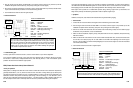
Hot wire type MAF sensor voltage should range from just over 2 V at idle to just over 4
V at WOT, and should dip slightly lower than idle voltage on full deceleration.
Vane type MAF sensor voltage should range from about 1 V at idle to just over 4 V at
WOT and not quite back to idle voltage on full deceleration.
Generally
,
on non-Toyota varieties, high airflow makes high voltage and low airflow
makes low voltage. When the sensor voltage output doesn’t follow airflow closely, the
waveform will show it and the engine operation will be noticeably affected.
MAX = 4.12 V
MIN = 680 mV
slow
accel.
Idle
Snap
accel.
Full
decel.