


2K
200
20M
2M
200K
20K
OHMS
750V AC
200V DC
COM
V
DWELL
4
CYL
5
CYL
6
CYL
8
CYL
4
CYL
5
CYL
6
CYL
8
CYL
2K
200
200
750
20
2
20M
2M
200K
20K
DC
V
A
C
V
OHMS
®
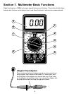
CP7676
R
P
M
X
10
750V AC
200V DC
COM
V
D
W
ELL
4
CYL
5
CYL
6
CYL
8
CYL
OFF
8
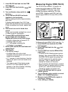
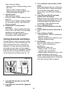
Measuring DC Voltage
This multimeter can be used to measure DC
voltages in the range from 0 to 200V. You
can use this multimeter to do any DC voltage
measurement called out in the vehicle
service manual. The most common
applications are measuring voltage drops,
and checking if the correct voltage arrived at
a sensor or a particular circuit.
6. View reading on display - Note range
setting for correct units.
NOTE: 200mV = 0.2V
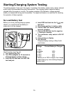
Measuring Resistance
Resistance is measured in electrical units
called ohms (Ω). The digital multimeter can
measure resistance from 0.1Ω to 20MΩ or
(20,000,000 ohms). Infinite resistance is
shown with a 1 on the left side of display
(See Setting the Range on page 6). You can
use this multimeter to do any resistance
measurement called out in the vehicle
service manual. Testing ignition coils, spark
plug wires, and some engine sensors are
common uses for the OHMS (Ω) function.
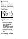
To measure Resistance (see Fig. 8):
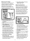
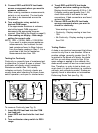
To measure DC Voltages (see Fig. 7):
1. Insert BLACK test lead into the COM
test lead jack.
2. Insert RED test lead into the test lead
jack.
3. Connect RED test lead to positive (+)
side of voltage source.
4. Connect BLACK test lead to negative
(-) side of voltage source.
NOTE: If you dont know which side is
positive (+) and which side is negative (-),
then arbitrarily connect the RED test lead
to one side and the BLACK to the other.
The multimeter automatically senses
polarity and will display a minus (-) sign
when negative polarity is measured. If you
switch the RED and BLACK test leads,
positive polarity will now be indicated on
the display. Measuring negative voltages
causes no harm to the multimeter.
5. Turn multimeter rotary switch to
desired voltage range.
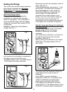
If the approximate voltage is unknown, start
at the largest voltage range and decrease
to the appropriate range as required. (See
Setting the Range on page 6)
1. Turn circuit power OFF.
To get an accurate resistance
measurement and avoid possible damage
to the digital multimeter and electrical
circuit under test, turn off all electrical
power in the circuit where the resistance
measurement is being taken.
2. Insert BLACK test lead into the COM
test lead jack.
3. Insert RED test lead into the
V
test
lead jack.
4. Turn multimeter rotary switch to 200Ω
range.
Touch RED and BLACK multimeter leads
together and view reading on display.
Display should read typically 0.2Ω to 1.5Ω.
If display reading was greater than 1.5Ω,
check both ends of test leads for bad
connections. If bad connections are
found, replace test leads.
Black
Fig. 7
Red Black
Fig. 8
Unknown
Resistance
Red