


4
CYL
5
CYL
6
CYL
8
CYL
2K
200
200
750
20
2
20M
2M
200K
20K
OHMS
R
P
M
X
1
0
750V AC
200V DC
COM
V
DWELL
4
CYL
5
CYL
6
CYL
8
CYL
4
CYL
5
CYL
6
CYL
8
CYL
2K
200
200
750
20
2
20M
2M
200K
20K
OHMS
R
P
M
X
1
0
750V AC
200V DC
COM
V
DWELL
4
CYL
5
CYL
6
CYL
8
CYL
20
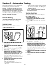
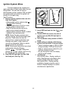
Ignition System Testing
The ignition system is responsible for providing the spark that ignites the fuel in the cylinder.
Ignition system components that the digital multimeter can test are the primary and secondary
ignition coil resistance, spark plug wire resistance, hall effect switches/sensors, reluctance pick-
up coil sensors, and the switching action of the primary ignition coil.
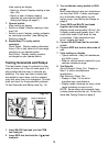
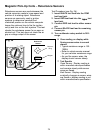
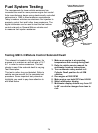
6. Connect test leads.
Connect RED test lead to primary
ignition coil positive (+) terminal.
Connect BLACK test lead to primary
ignition coil negative (-) terminal.
Refer to vehicle service manual for
location of primary ignition coil terminals.
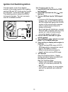
7. View reading on display.
Subtract test lead resistance found in Step
5 from above reading.
8. If vehicle is DIS, repeat Steps 6 and 7
for remaining ignition coils.
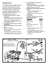
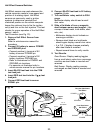
Fig. 20
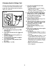
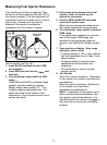
Fig. 21
Black
Secondary
Coil
Primary
Coil
Red
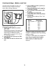
4. Insert RED test lead into the
V
test lead jack.
5. Turn multimeter rotary switch
to 200Ω range.
Touch RED and BLACK test
leads together and view reading
on display.
Display should read typically
0.2Ω to 1.5Ω.
If display reading was greater
than 1.5Ω, check both ends of
test leads for bad connections.
If bad connections are found,
replace test leads.
9. Test Results - Primary Coil
Typical resistance range of
primary ignition coils is 0.3 -
2.0Ω.
Refer to vehicle service manual
for your vehicle's resistance
range.
10.Turn multimeter rotary switch
to 200KΩ range (see Fig. 21).
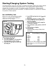
Ignition Coil Testing
This test measures the resistance of the
primary and secondary of an ignition coil. This
test can be used for distributorless ignition
systems (DIS) provided the primary and
secondary ignition coil terminals are easily
accessible.
Test Procedure:
1. If engine is HOT let it COOL down
before proceeding.
2. Disconnect ignition coil from ignition
system.
3. Insert BLACK test lead into the COM
test lead jack. (See Fig. 20.)
Typical Cylindrical
Ignition Coil
Red
Primary
Coil
Secondary
Coil
Black
Typical Cylindrical
Ignition Coil