


4
CYL
5
CYL
6
CYL
8
CYL
OFF
2K
200
200
750
20
2
20M
2M
200K
20K
DC
V
A
C
V
OHMS
R
P
M
X
1
0
750V AC
200V DC
COM
V
DWELL
4
CYL
5
CYL
6
CYL
8
CYL
2K
200
20M
2M
200K
20K
OHMS
750V AC
200V DC
COM
V
DWELL
4
CYL
5
CYL
6
CYL
8
CYL
13
Section 2. Automotive Testing
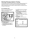
The digital multimeter is a very useful tool for
trouble-shooting automotive electrical
systems. This section describes how to use
the digital multimeter to test the starting and
charging system, ignition system, fuel system,
and engine sensors. The digital multimeter
can also be used for general testing of fuses,
switches, solenoids, and relays.
General Testing
The digital multimeter can be used to test
fuses, switches, solenoids, and relays.
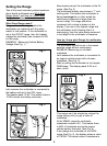
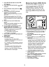
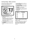
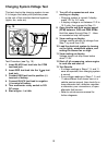
Testing Fuses
This test checks to see if a fuse is blown.
To test Fuses (see Fig. 13):
Fuse is blown if display reading indicates
an overrange condition. (see Setting the
Range on page 6)
NOTE: Always replace blown fuses with
same type and rating.
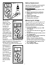
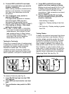
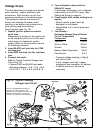
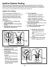
Testing Switches
This test checks to see if a switch Opens
and Closes properly.
To test Switches (see Fig. 14):
1. Insert BLACK test lead into the COM
test lead jack.
2. Insert RED test lead into the test lead
jack.
1. Insert BLACK test lead into the COM
test lead jack.
2. Insert RED test lead into the
V
test
lead jack.
3. Turn multimeter rotary switch to 200Ω
range.
4. Touch RED and BLACK test leads
together and view reading on display.
Display should read typically 0.2Ω to 1.5Ω.
If display reading was greater than 1.5Ω,
check both ends of test leads for bad
connections. If bad connections are found,
replace test leads.
5. Connect RED and BLACK test leads to
opposite ends of fuse.
View reading on display:
Fuse is good if display reading is less
than 10Ω.
3. Turn multimeter rotary switch to 200Ω
range.
4. Touch RED and BLACK test leads
together and view reading on display.
Display should read typically 0.2Ω to 1.5Ω.
If display reading was greater than 1.5Ω,
check both ends of test leads for bad
connections. If bad connections are found,
replace test leads.
5. Connect BLACK test lead to one side of
switch.
6. Connect RED test lead to other side of
switch.
Fig. 13
Fuse
Red
Black
Fig. 14
Typical
"Push"
Button
Switch
Red
Black