


4
CYL
5
C
YL
6
C
YL
8
C
YL
2K
200
200
750
20
2
20M
2M
200K
20K
DC
V
AC
V
OHMS
R
P
M
X
1
0
750V AC
200V DC
COM
V
DWELL
4
CYL
5
CYL
6
CYL
8
CYL
OFF
16
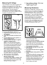
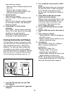
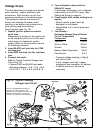
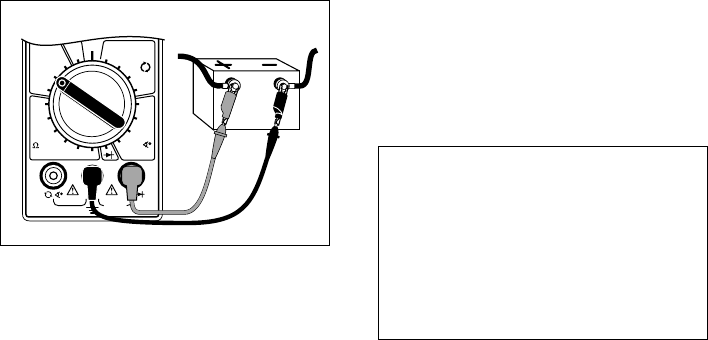
Cranking Voltage - Battery Load Test
This test checks the battery to see if it is
delivering enough voltage to the starter
motor under cranking conditions.
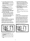
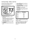
4. Connect RED test lead to positive (+)
terminal of battery.
5. Connect BLACK test lead to negative
(-) terminal of battery.
6. Turn multimeter rotary switch to 20V
DC range.
7. Crank engine for 15 seconds
continuously while observing display.
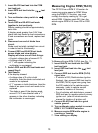
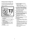
8. Test Results.
Compare display reading in Step 7 with
chart below.
Fig. 17
Voltage Temperature
9.6V or greater 70 °F and Above
9.5V 60 °F
9.4V 50 °F
9.3V 40 °F
9.1V 30 °F
8.9V 20 °F
8.7V 10 °F
8.5V 0 °F
If voltage on display corresponds to above
voltage vs. temperature chart, then cranking
system is normal.
If voltage on display does not correspond to
chart, then it is possible that the battery,
battery cables, starting system cables,
starter solenoid, or starter motor are
defective.
Red
Black
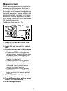
Test Procedure (see Fig. 17):
1. Disable ignition system so vehicle
wont start.
Disconnect the primary of the ignition coil
or the distributor pick-up coil or the cam/
crank sensor to disable the ignition
system. Refer to vehicle service manual
for disabling procedure.
2. Insert BLACK test lead into the COM
test lead jack.
3. Insert RED test lead into the test lead
jack.