


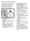

4
CYL
5
C
YL
6
C
YL
8
CYL
2K
200
200
750
20
2
20M
2M
200K
20K
OHMS
R
P
M
X
1
0
750V AC
200V DC
COM
V
DWELL
4
CYL
5
CYL
6
CYL
8
CYL
31
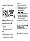
Position Type Sensors
Position sensors are potentiometers or a type of
variable resistor. They are used by the computer to
determine position and direction of movement of a
mechanical device. Typical position sensor
applications are throttle position sensors, EGR
valve position sensors, and vane air flow sensors.
7. Move RED test lead to sensor
SIGNAL pin.
Refer to vehicle service manual for
location of sensor SIGNAL pin.
8. Operate Sensor.
Throttle Position Sensor:
Slowly move throttle linkage from
closed to wide open position.
Depending on hook-up, the display
reading will either increase or
decrease in resistance.
The display reading should either
start at or end at the approximate
resistance value measured in Step 6.
Some throttle position sensors have
an Idle or Wide Open Throttle (WOT)
switch in addition to a potentiometer.
To test these switches, follow the
Testing Switches test procedure on
page 13.
When you are told to operate switch,
then move throttle linkage.
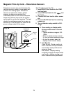
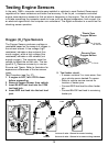
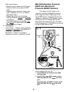
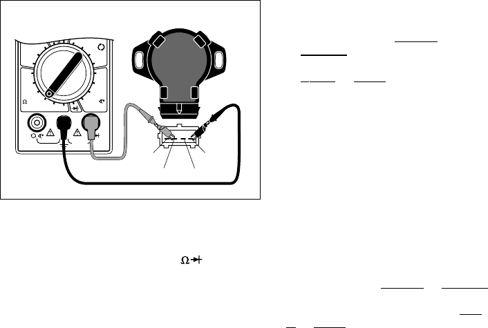
Vane Air Flow Sensor:
Fig. 29
Test Procedure (see Fig. 29):
1. Insert BLACK test lead into the COM
test lead jack.
2. Insert RED test lead into the
V
test
lead jack.
3. Disconnect wiring harness from
sensor.
4. Connect Test Leads.
Connect RED test lead to sensor
POWER pin.
Connect BLACK test lead to sensor
GROUND pin.
Refer to vehicle service manual for
location of sensor POWER and
GROUND pins.
5. Turn multimeter rotary switch to 20KΩ
range.
6. View and record reading on display.
Display should read some resistance
value.
If multimeter is overranging, adjust the
range accordingly. (See Setting the
Range on page 6.)
If multimeter overranges on largest
range, then sensor is an open circuit
and is defective.
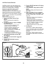
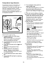
Typical Toyota Throttle
Position Sensor
Black
POWER
SIGNAL IDLE SWITCH
Slowly open vane door from closed to
open by pushing on it with a pencil or
similar object. This will not harm sensor.
Depending on hook-up, the display
reading will either increase or decrease
in resistance.
The display reading should either start
at or end at the approximate resistance
value measured in Step 6.
Some vane air flow sensors have an
idle switch and an intake air
temperature sensor in addition to a
potentiometer.
To test idle switch see Testing Switches
on page 13.
When you are told to operate switch,
then open vane door.
To test intake air temperature sensor
see Temperature Type Sensors on page
30.
Red
GROUND