


29
Turn multimeter rotary switch to 200Ω
range.
View reading on display.
Compare reading to manufacturer's
specification in vehicle service manual.
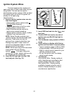
Remove both test leads from sensor.
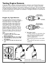
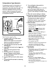
6. Connect BLACK test lead to sensor
GROUND pin.
If sensor is 1-wire or 3-wire, then
GROUND is sensor housing.
If sensor is 2-wire or 4-wire, then
GROUND is in sensor wiring harness.
Refer to vehicle service manual for
Oxygen Sensor wiring diagram.
7. Connect RED test lead to sensor
SIGNAL pin.
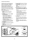
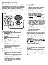
8. Test Oxygen Sensor.
Turn multimeter rotary switch to...
2V range for Zirconia Type Sensors.
200Ký range for Titania Type Sensors.
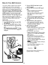
Light propane torch.
Firmly grasp sensor with a pair of
locking pliers.
Thoroughly heat sensor tip as hot as
possible, but not glowing. Sensor tip
must be at 660°F to operate.
Completely surround sensor tip with
flame to deplete sensor of oxygen (Rich
Condition).
Multimeter display should read...
0.6V or greater for Zirconia Type
Sensors.
an Ohmic(Resistance) value for Titania
Type Sensors. Reading will vary with
flame temperature.
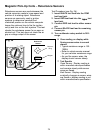
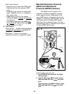
While still applying heat to sensor, move
flame such that oxygen can reach
sensor tip (Lean Condition).
Multimeter display should read...
0.4V or less for Zirconia Type Sensors.
an overrange condition for Titania Type
Sensors. (See Setting the Range on
page 6.)
9. Repeat Step 8 a few times to verify
results.
10.Extinguish Flame, let sensor cool, and
remove test leads.
11. Test Results.
Good Sensor:
Heater Circuit resistance is within
manufacturer's specification.
Oxygen Sensor output signal changed
when exposed to a rich and lean
condition.
Bad Sensor:
Heater Circuit resistance is not within
manufacturer's specification.
Oxygen Sensor output signal did not
change when exposed to a rich and lean
condition.
Oxygen sensor output voltage takes
longer than 3 seconds to switch from a
rich to a lean condition.