


OFF
4
CYL
5
C
YL
6
CYL
8
CYL
OFF
2K
200
200
750
20
2
20M
2M
200K
20K
DC
V
AC
V
OHMS
R
P
M
X
1
0
750V AC
200V DC
COM
V
DWELL
4
CYL
5
CYL
6
CYL
8
CYL
10
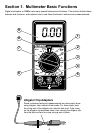
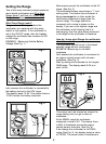
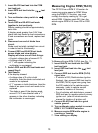
Measuring Engine RPM (TACH)
The CP7676 has a RPM X 10 function for
measuring engine speed or RPM. When
using the RPM X 10 function, you must
multiply the display reading by 10 to get
actual RPM. If display reads 200, then the
actual engine RPM is 10 times 200 or 2000
RPM.
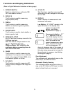
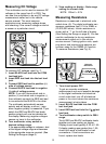
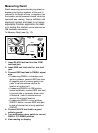
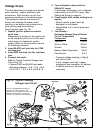
To Measure Engine RPM (TACH) (see Fig. 11):
1. Insert BLACK test lead into the COM
test lead jack.
2. Insert RED test lead into the test
lead jack.
3. Connect RED test lead to RPM (TACH)
signal wire.
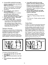
If vehicle is DIS (Distributorless Ignition
System), then connect RED test lead to
the RPM (TACH) signal wire going from
the DIS module to the vehicle engine
computer. (refer to vehicle service
manual for location of this wire)
For all vehicles with distributors, connect
RED test lead to negative side of primary
ignition coil. (refer to vehicle service
manual for location of ignition coil)
4. Connect BLACK test lead to a good
vehicle ground.
5. Turn multimeter rotary switch to correct
RPM X 10 CYLINDER selection.
6. Measure engine RPM while engine is
cranking or running.
7. View reading on display.
Fig. 11
Black
Ground
Red
Typical
Ignition
Coil
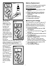
1. Insert BLACK test lead into the COM
test lead jack.
2. Insert RED test lead into the
V
test
lead jack.
3. Turn multimeter rotary switch to
function.
4. Touch RED and BLACK test leads
together to test continuity.
Display reading should be approximately
zero volts.
If display reads greater than 0.5V, then
check both test leads for bad connections.
If bad connections are found, replace test
leads.
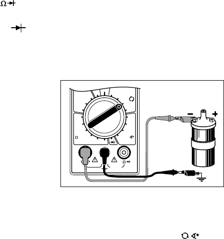
5. Disconnect one end of diode from
circuit.
Diode must be totally isolated from circuit
in order to test its functionality.
6. Connect RED and BLACK test leads
across diode and view display.
Display will show one of three things:
A typical voltage drop of around 0.7V.
A voltage drop of 0 volts.
A 1 will appear indicating the
multimeter is overranged.
7. Switch RED and BLACK test leads and
repeat Step 6.
8. Test Results
If the display showed:
A voltage drop of 0 volts in both
directions, then the diode is shorted and
needs to be replaced.
A 1 appears in both directions, then the
diode is an open circuit and needs to be
replaced.
The diode is good if the display reads
around 0.7V in one direction and a 1
appears in the other direction indicating
the multimeter is overranged.