


4
C
Y
L
5
C
Y
L
6
C
Y
L
8
C
Y
L
2K
200
200
750
20
2
20M
2M
200K
20K
OHM
S
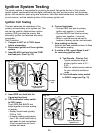
RPM
X10
750V AC
200V DC
COM
V
DWELL
4
C
Y
L
5
C
Y
L
6
C
Y
L
8
C
Y
L
28
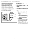
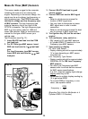
Testing Engine Sensors
In the early 1980s, computer controls were installed in vehicles to meet Federal Government
regulations for lower emissions and better fuel economy. To do its job, a computer-controlled
engine uses electronic sensors to find out what is happening in the engine. The job of the sensor
is to take something the computer needs to know, such as engine temperature, and convert it to
an electrical signal which the computer can understand. The digital multimeter is a useful tool for
checking sensor operation.
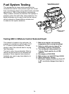
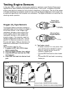
Oxygen (O
2
) Type Sensors
The Oxygen Sensor produces a voltage or
resistance based on the amount of oxygen in
the exhaust stream. A low voltage (high
resistance) indicates a lean exhaust (too
much oxygen), while a high voltage (low
resistance) indicates a rich exhaust (not
enough oxygen). The computer uses this
voltage to adjust the air/fuel ratio. The two
types of O
2
Sensors commonly in use are
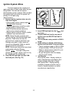
Zirconia and Titania. Refer to illustration for
appearance differences of the two sensor
types.
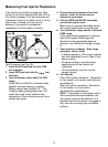
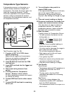
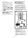
Test Procedure (see Fig. 27):
1. If engine is HOT, let it COOL down
before proceeding.
2. Remove Oxygen Sensor from vehicle.
3. Insert BLACK test lead into the COM
test lead jack.
4. Insert RED test lead into the test lead
jack.
Titania-Type
Oxygen Sensor
Zirconia-Type
Oxygen Sensor
Exposed
flat element
Flutes
Fig. 27
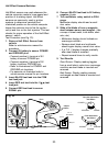
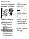
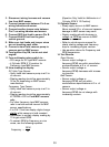
5. Test heater circuit.
If sensor contains 3 or more wires, then
your vehicle uses a heated O
2
sensor.
Refer to vehicle service manual for
location of heater pins.
Connect RED test lead to either heater
pin.
Connect BLACK test lead to remaining
heater pin.
Rich
Lean
Red
Black
1-wire or 3-wire: Ground is sensor housing
2-wire or 4-wire: Ground is in sensor wiring harness
Ground