


4
CYL
5
CYL
6
CYL
8
CYL
2K
200
200
750
20
2
20M
2M
200K
20K
DC
V
AC
V
OHMS
R
P
M
X
1
0
750V AC
200V DC
COM
V
DWELL
4
CYL
5
CYL
6
CYL
8
CYL
OFF
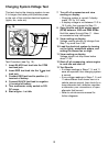
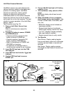
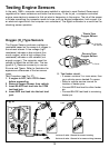
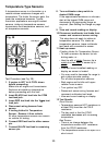
Ignition Coil Switching Action
25
This test checks to see if the negative
terminal of the primary ignition coil is getting
switched ON and OFF via the ignition module
and camshaft / crankshaft position sensors.
This switching action is where the RPM or
tach signal originates. This test is primarily
used for a no start condition.
Test Procedure (see Fig. 25):
1. Insert BLACK test lead into the COM
test lead jack.
2. Insert RED test lead into the test
lead jack.
3. Connect RED test lead to TACH signal
wire.
If vehicle is DIS (Distributorless Ignition
System), then connect RED test lead to
the TACH signal wire going from the DIS
module to the vehicle engine computer.
(refer to vehicle service manual for
location of this wire)
For all vehicles with distributors, connect
RED test lead to negative side of primary
ignition coil. (refer to vehicle service
manual for location of ignition coil)
4. Connect BLACK test lead to a good
vehicle ground.
5. Turn multimeter rotary switch to correct
RPM X 10 CYLINDER selection.
6. View reading on display while engine is
cranking.
Typical cranking RPM range is 50-275
RPM depending on temperature, size of
engine, and battery condition.
Refer to vehicle service manual for
specific vehicle cranking RPM range.
7. Test Results.
Good Coil Switching Action: Display
reading indicated a value consistent with
manufacturers specifications.
Bad Coil Switching Action:
Display read zero RPM, meaning the
ignition coil is not being switched ON
and OFF.
Check ignition system for wiring defects,
and test the camshaft and crankshaft
sensors.
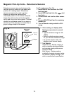
Typical
Ignition
Coil
Fig. 25
Ground
Black
Red