


1
10
2
4
5
6 8
7
7
9
8
9
6
2
4
5
3
3
17
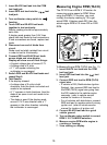
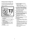
Voltage Drops
5. Turn multimeter rotary switch to
200mV DC range.
If multimeter overranges, turn multimeter
rotary switch to the 2V DC range. (See
Setting the Range on page 6)
6. Crank engine until steady reading is on
display.
Record results at each point as
displayed on multimeter.
Repeat Step 4 & 5 until all points are
checked.
7. Test Results
Estimated Voltage Drop of Starter
Circuit Components
Component Voltage
Switches 300mV
Wire or Cable 200mV
Ground 100mV
Battery Cable Connectors 50mV
Connections 0.0 V
Compare voltage readings in Step 6
with above chart.
If any voltages read high, inspect
component and connection for defects.
If defects are found, service as
necessary.
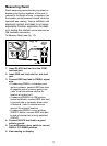
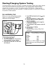
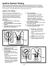
This test measures the voltage drop across
wires, switches, cables, solenoids, and
connections. With this test you can find
excessive resistance in the starter system.
This resistance restricts the amount of
current that reaches the starter motor
resulting in low battery load voltage and a
slow cranking engine at starting.
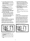
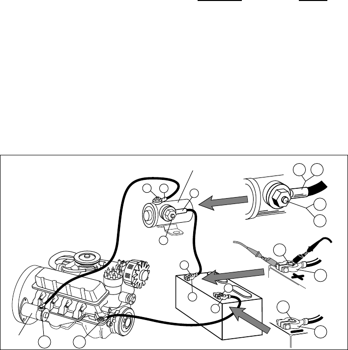
Test Procedure (see Fig. 18):
1. Disable ignition system so vehicle
wont start.
Disconnect the primary of the ignition coil
or the distributor pick-up coil or the cam/
crank sensor to disable the ignition
system. Refer to vehicle service manual
for disabling procedure.
2. Insert BLACK test lead into the COM
test lead jack.
3. Insert RED test lead into the test lead
jack.
4. Connect test leads.
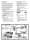
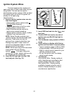
Refer to Typical Cranking Voltage Loss
Circuit (Fig. 18).
Connect RED and BLACK test leads
alternately between 1 & 2, 2 & 3, 4 & 5,
5 & 6, 6 & 7, 7 & 8, 8 & 9, and 8 & 10.
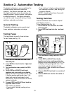
Red
Black
Fig. 18 Typical Cranking
Voltage Loss Circuit
Solenoid
This is a representative sample of
one type of cranking circuit. Your
vehicle may use a different circuit with
different components or locations.
Consult your vehicle service manual.
Starter