


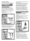


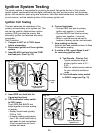
View reading on display:
Switch is closed if display reading is less
than 10Ω.
Switch is open if display reading
indicates an overrange condition. (see
Setting the Range on page 6)
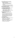
7. Operate switch.
View reading on display:
Switch is closed if display reading is less
than 10Ω.
Switch is open if display reading indicates
an overrange condition. (see Setting the
Range on page 6)
8. Repeat Step 7 to verify switch
operation.
Good Switch: Display reading alternates
from a 10Ω or less value to an overrange
condition as you operate switch.
Bad Switch: Display reading remains
unchanged as you operate switch.
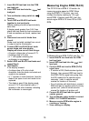
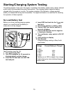
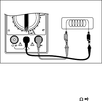
Testing Solenoids and Relays
This test checks to see if a solenoid or relay
have a broken coil. If the coil tests good, it is
still possible that the relay or solenoid are
defective. The relay can have contacts that
are welded or worn down, and the solenoid
may stick when the coil is energized. This test
does not check for those potential problems.
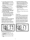
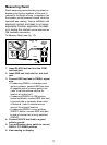
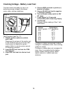
To test Solenoids and Relays (see Fig. 15):
14
1. Insert BLACK test lead into the COM
test lead jack.
2. Insert RED test lead into the
V
test
lead jack.
3. Turn multimeter rotary switch to 200Ω
range.
Most solenoids and relay coil resistances
are less than 200Ω. If meter overranges,
turn multimeter rotary switch to next
higher range. (see Setting the Range on
page 6)
4. Touch RED and BLACK test leads
together and view display.
Display should read typically 0.2Ω to 1.5Ω.
If display reading was greater than 1.5Ω,
check both ends of test leads for bad
connections. If bad connections are
found, replace test leads.
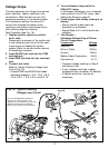
5. Connect BLACK test lead to one side
of coil.
6. Connect RED test lead to other side of
coil.
7. View reading on display.
Typical solenoid / relay coil resistances
are 200Ω or less.
Refer to vehicle service manual for your
vehicles resistance range.
8. Test Results
Good Solenoid / Relay Coil: Display in
Step 7 is within manufacturers
specification.
Bad Solenoid / Relay Coil:
Display in Step 7 is not within
manufacturers specifications.
Display reads overrange on every ohms
range indicating an open circuit.
NOTE: Some relays and solenoids have
a diode placed across the coil. To test this
diode see Testing Diodes on page 9.
2K
200
20M
2M
200K
20K
OHMS
750V AC
200V DC
COM
V
DWELL
4
CYL
5
CYL
6
CYL
8
CYL
Fig. 15
Relay or Solenoid
Red
Black