


C
B
A
4
C
Y
L
5
C
Y
L
6
C
Y
L
8
C
Y
L
2K
200
200
750
20
2
20M
2M
200K
20K
DC
V
AC
V
OHMS
R
P
M
X
10
750V AC
200V DC
COM
V
DWELL
4
C
Y
L
5
C
Y
L
6
C
Y
L
8
C
Y
L
3
0
2
5
20
15
5
0
10
VACUUM PUMP
OFF
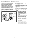
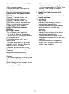
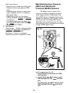
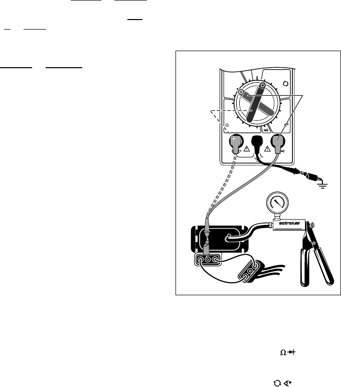
EGR Valve Position
Remove vacuum hose from EGR valve.
Connect hand vacuum pump to EGR
valve.
Gradually apply vacuum to slowly open
valve. (Typically, 5 to 10 in. of vacuum
fully opens valve.)
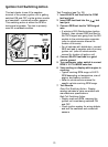
Depending on hook-up, the display
reading will either increase or decrease
in resistance.
The display reading should either start
at or end at the approximate resistance
value measured in Step 6.
9. Test Results.
Good Sensor: Display reading gradually
increases or decreases in resistance as
sensor is opened and closed.
Bad Sensor: There is no change in
resistance as sensor is opened or closed.
32
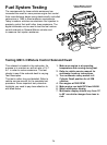
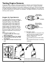
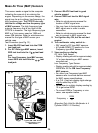
Manifold Absolute Pressure
(MAP) and Barometric
Pressure (BARO) Sensors
This sensor sends a signal to the
computer indicating atmospheric pressure
and/or engine vacuum. Depending on the
type of MAP sensor, the signal may be a dc
voltage or a frequency. GM, Chrysler, Honda
and Toyota use a dc voltage MAP sensor,
while Ford uses a frequency type. For other
manufacturers refer to vehicle service manual
for type of MAP sensor used.
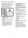
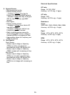
Test Procedure (see Fig. 30):
1. Insert BLACK test lead into the COM
test lead jack.
2. For DC Volts type MAP sensor, insert
RED test lead into the
V
test lead
jack.
For Frequency type MAP sensor, insert
RED test lead into the test lead
jack.
Fig. 30
Typical GM
MAP Sensor
Black
To
Computer
Red
Ground
Frequency
Only
DC
Only
Red