


4
CYL
5
CYL
6
CYL
8
CYL
2K
200
200
750
20
2
20M
2M
200K
20K
OHMS
R
P
M
X
1
0
750V AC
200V DC
COM
V
DWELL
4
CYL
5
CYL
6
CYL
8
CYL
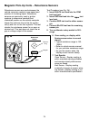
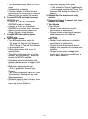
Magnetic Pick-Up Coils Reluctance Sensors
24
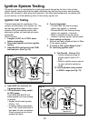
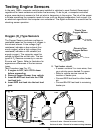
Reluctance sensors are used whenever the
vehicle computer needs to know speed and
position of a rotating object. Reluctance
sensors are commonly used in ignition
systems to determine camshaft and
crankshaft position so the vehicle computer
knows the optimum time to fire the ignition
coil(s) and turn on the fuel injectors. This test
checks the reluctance sensor for an open or
shorted coil. This test does not check the air
gap or voltage output of the sensor.
Fig. 24
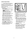
Test Procedure (see Fig. 24):
1. Insert BLACK test lead into the COM
test lead jack.
2. Insert RED test lead into the
V
test
lead jack.
3. Connect RED test lead to either sensor
pin.
4. Connect BLACK test lead to remaining
sensor pin.
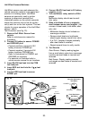
5. Turn multimeter rotary switch to 2KΩ
range.
6. View reading on display while
flexing sensor wires in several
places.
Typical resistance range is 150 -
1000Ω.
Refer to vehicle service manual
for your vehicles resistance range.
As you flex sensor wires, the
display should remain steady.
7. Test Results
Good Sensor: Display reading is
within manufacturers specification
and remains steady while sensor
wires are flexed.
Bad Sensor: Display reading
erratically changes as sensor wires
are flexed or display reading is not
within manufacturers specification.
Reluctance
Sensor
Reluctor
Ring
Magnet
Red
Black