


4
CYL
5
C
YL
6
CYL
8
CYL
2K
200
200
750
20
2
20M
2M
200K
20K
DC
V
AC
V
OHMS
R
P
M
X
1
0
750V AC
200V DC
COM
V
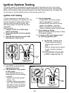
DWELL
4
CYL
5
CYL
6
CYL
8
CYL
OFF
18
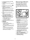
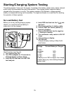
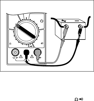
Charging System Voltage Test
This test checks the charging system to see
if it charges the battery and provides power
to the rest of the vehicles electrical systems
(lights, fan, radio etc).
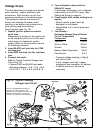
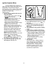
Fig. 19
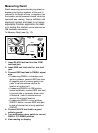
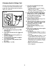
7. Turn off all accessories and view
reading on display.
Charging system is normal if display
reads 13.2 to 15.2 volts.
If display voltage is not between 13.2 to
15.2 volts, then proceed to Step 13.
8. Open throttle and Hold engine speed
(RPM) between 1800 and 2800 RPMs.
Hold this speed through Step 11 - Have
an assistance help hold speed.
9. View reading on display.
Voltage reading should not change from
Step 7 by more than 0.5V.
10.Load the electrical system by turning
on the lights, windshield wipers, and
setting the blower fan on high.
11.View reading on display.
Voltage should not drop down below
about 13.0V.
12.Shut off all accessories, return engine
to curb idle and shut off.
13.Test Results.
If voltage readings in Steps 7, 9, and 11
were as expected, then charging system
is normal.
If any voltage readings in Steps 7, 9, and
11 were different then shown here or in
vehicle service manual, then check for a
loose alternator belt, defective regulator
or alternator, poor connections, or open
alternator field current.
Refer to vehicle service manual for
further diagnosis.
Red
Black
Test Procedure (see Fig. 19):
1. Insert BLACK test lead into the COM
test lead jack.
2. Insert RED test lead into the
V
test
lead jack.
3. Connect RED test lead to positive (+)
terminal of battery.
4. Connect BLACK test lead to negative
(-) terminal of battery.
5. Turn multimeter rotary switch to 20V
DC range.
6. Start engine - Let idle.