28
Main Pages
RMI Page ( Land/Water Mode)
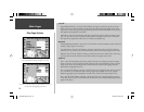
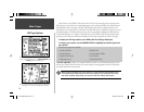
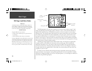
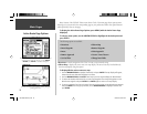
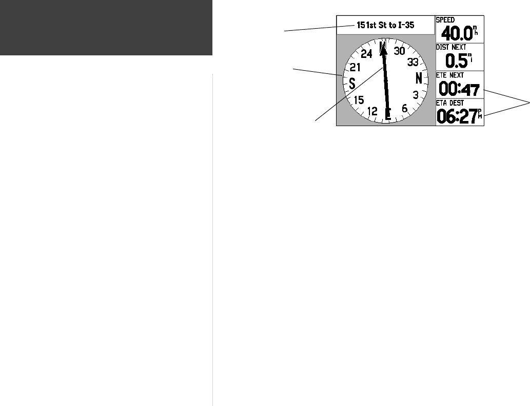
The RMI Page appears only when the GPSMAP 196 is in Land or Water modes (see page 7), and
replaces the HSI Page in the main page sequence. Whenever a ‘Goto’ or route has been activated, the
graphic RMI indicates bearing to the destination waypoint (or the next waypoint in a route) using a
‘bearing pointer’. The rotating compass card indicates your current ground track at the top of the page.
The compass ring and pointer arrow work independently to show, at a glance, the direction of your
movement and the direction to your destination. For instance, if the arrow points up, you are going
directly to the waypoint. If the arrow points any direction other than up, turn toward the arrow until it
points up, then continue in that direction. As you reach your destination, the bearing pointer will swing
from top to bottom to indicate waypoint passage.
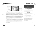
The RMI Page changes slightly between Land and Water modes. In Land mode, the graphic RMI
is slightly smaller to accommodate turn instructions at the top of the page. When using optional
MapSource MetroGuide or City Select data in Land Mode, the GPSMAP 196 can provide automatic
turn-by-turn instructions. The distance, direction and name of the next turn will appear at the top of
the page, directly above the graphic RMI. In Water Mode, this text area indicates the name of the next
waypoint in a ‘Goto’ or route.
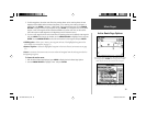
By default, four user-selectable data fi elds appear along the right-hand side of the page showing:
distance and time to next waypoint, current ground speed and time of arrival at destination. Each data
fi eld may be confi gured to display any one of over forty data options, or you can display ten smaller text
data fi elds, using the RMI Page Options.
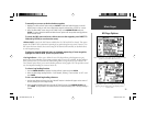
What is it?
The RMI Page displays a graphic Radio Magnetic Indicator (or,
bearing indicator), similar to a mechanical instrument found in
many aircraft. The graphic RMI only appears in Land and Water
modes and is replaced with a graphic HSI in Aviation Mode.
How does it work?
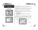
The graphic RMI consists of two elements:
• a rotating compass card that depicts your ground track at the
top of the page.
• a pointer that indicates the bearing to your destination.
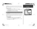
The graphic RMI differs from the graphic HSI in the function of the
pointer. Recall that the pointer for the HSI indicates the intended
course and stays fi xed on this course heading. The pointer for the
RMI indicates the bearing to your destination, from your current
position, and constantly updates as your position changes. In this
manner, it operates similar to an ADF instrument in an aircraft.
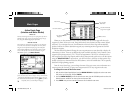
Rotating Compass
Card
Driving
Instructions
Bearing Pointer
User-selectable
Data Fields
190-00283-00Backup.indd 28 12/8/2002, 8:09:03 PM


