


23
Main Pages
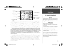
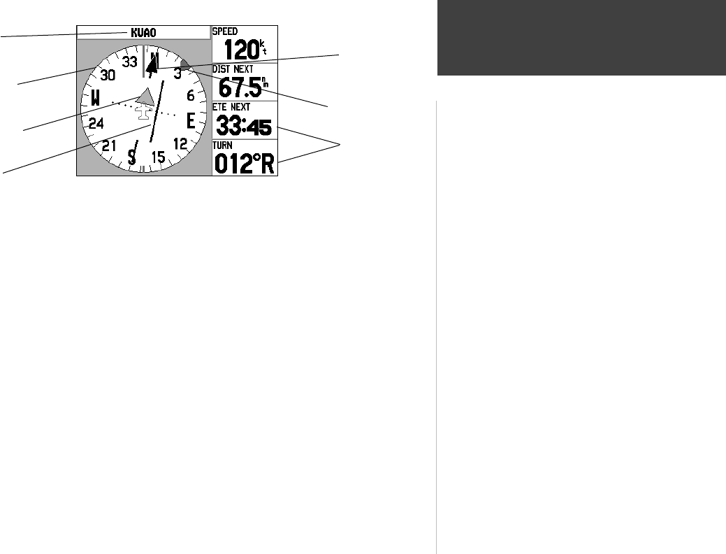
HSI Page ( Aviation Mode)
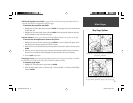
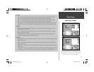
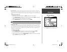
The HSI Page appears only when the GPSMAP 196 is in Aviation Mode (see page 7). The graphic
HSI depicts the desired course to the destination waypoint (or the next waypoint in a route), current
ground track, off course error and a TO/FROM indication. The rotating compass card indicates your
current ground track at the top of the page. The desired course pointer and course deviation needle
indicate the desired course and whether or not you’re on the desired course. A bug indicator provides
course to steer (CTS) information, guiding you back to the desired course should you stray off course.
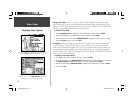
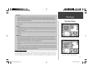
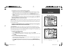
The course deviation scale appears behind the course deviation needle. If you move off course, the
needle will indicate how far off course you are, left or right, based upon its placement along the course
deviation scale. To get back on course and center the needle, simply steer toward the needle. The course
deviation scale setting is adjustable for ±0.25, 1.25 or 5.0 (nautical mile/statute mile/kilometer) full
scale defl ection. The default setting is 1.25, which represents the distance from the center of the CDI to
full left or right limits.
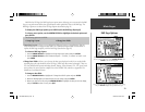
As you reach your destination, a TO/FROM indicator at the center of the HSI will indicate waypoint
passage. By default, four user-selectable data fi elds appear along the right-hand side of the page show-
ing: distance and time to next waypoint, current speed and turn direction. Each data fi eld may be
confi gured to display any one of 40 data options, or you can display ten data fi elds with smaller text
in each fi eld (using the HSI Page Options). The default data terms and all optional data selections are
described in Appendix D.
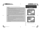
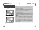
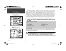
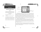
What is it?
The HSI and Panel Pages display a graphic Horizontal Situation
Indicator, similar to a mechanical instrument found in many air-
craft. The graphic HSI appears in Aviation Mode and is replaced
with a graphic RMI in Land and Water modes.
How does it work?
The graphic HSI consists of several elements:
• a rotating compass card that depicts your ground track at the
top of the page.
• a pointer that indicates the course heading to your destination.
• a course deviation needle and deviation scale that indicates
how far left or right of the intended course you are.
• a TO/FROM fl ag which indicates waypoint passage.
• a ‘Bug’ reference along the outer edge of the compass card that
has selectable functions.
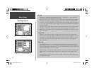
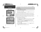
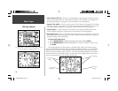
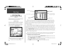
NOTE: One key difference between a mechanical HSI and what
appears on the graphic HSI is the interpretation of the rotating
compass card. On the graphic HSI the top of the compass card
depicts your ground track. On a mechanical instrument the
compass card depicts aircraft heading. In a crosswind, these two
references will be different.
Rotating Compass
Card
Destination
Waypoint
To/From Flag
Course Deviation
Needle
Desired Course
Pointer
Bug Indicator
User-selectable
Data Fields
190-00283-00Backup.indd 23 12/8/2002, 8:09:00 PM