


84
Reference Manual
00809-0700-4530, Rev AA
Appendix A: Checklists
September 2013
Checklists
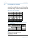
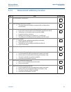
A.2.3 Troubleshooting procedure
Step Task Completed
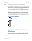
1 Voltage at transmitter terminals are checked
2 DCS trends are checked
3 Tank survey is done to identify the application
4 Basic errors (cables, transmitter diagnostics etc.) are checked
a. Cables are connected properly
b. Diagnostic messages are checked (in RRM)
5 Verification procedure is executed, if necessary
(as described in the measurement validation procedure)
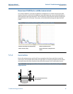
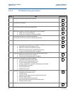
6 Echo-curve analysis is performed and analyzed
7 Threshold settings are checked (Rosemount 3300 and 5300 Series)
a. Automatic threshold settings are used
b. Dielectric constants are entered correctly
c. Measure & Learn function is applied (if necessary)
d. Custom threshold adjustments are applied
8 Threshold settings are checked (Rosemount 5400 and 5600 Series)
a. Measure & Learn function is applied
b. Custom threshold adjustments are applied
9 Echo-curve is checked for common problems
a. Threshold is below the surface peak
b. Disturbance is misinterpreted as level
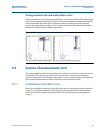
c. Incorrect reading due to bent probe
d. Incorrect reading due to probe contacting the nozzle wall
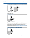
e. Possible build-up on probe
f. Strong antenna echo
g. Weak antenna echo
10 Sources of measurement errors are checked
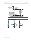
a. Installation and location errors
b. Tank geometry
c. Probe End Pulse offset (only for Probe End Projection)
d. Analog output settings
e. Incorrect static vapor compensation
f. Reconciling radar with other level measurements
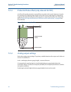
g. Chamber measurement
11 Measurement validation procedure is completed to verify the transmitter's integrity