


47
Reference Manual
00809-0700-4530, Rev AA
Section 3: Commissioning
September 2013
Commissioning
3.3.7 Signal Quality Metrics (Rosemount 5300 and 5400 Series)
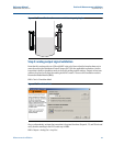
Signal Quality Metrics (SQM) indicates the surface signal integrity compared to the noise. It can
be used to schedule maintenance to clean the probe or detect and monitor turbulence, boiling,
and foam.
The Rosemount 5300 Series with Diagnostics Suite option and the Rosemount 5400 Series have
the SQM function. See the Rosemount 5300 Series and Rosemount 5400 Series Reference
Manuals for set-up details (Document No. 00809-0100-4530 and 00809 -0100-4026).
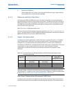
To view SQM in RRM:
RRM > Tools > Device Display > Signal Quality Metrics
NOTE:
If SQM is not supported or disabled, the signal quality and surface/noise margin will always be
set to 0.
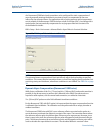
SQM can be shown on the LCD panel, see "Operation" in the Rosemount 5300 Series and
Rosemount 5400 Series Reference Manuals (Document No. 00809-0100-4530 and
00809-0100-4026). SQM can be assigned to transmitter variables (SV, TV, or QV). In RRM, this
can be done by selecting:
RRM > Setup > Output
Variables can be sent to the Distributed Control System (DCS) to trigger an alarm. Suitable
trigger levels vary from application to application. Guidelines for appropriate values can be
determined by logging SQM over time and viewing minimum/maximum values. The signal
quality alarm trigger value should be at least 1, but a better guideline is 2-3.
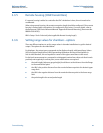
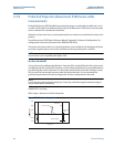
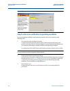
3.3.8 Configuration for process conditions
The Rosemount 5400 and 5600 Series have advanced configuration options for different
process conditions, such as Foam, Turbulent Surface, Rapid Level Changes, or Solid Product (only
Rosemount 5600 Series). This means that the transmitter database configuration is optimized
for the process condition selected e.g. solids measurements. Additional adjustments of the
database might in some cases become necessary for solids measurement. In such cases, contact
a Rosemount representative for further details on how to proceed.
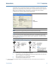
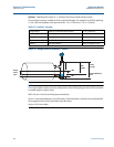
By selecting the suitable option for the process condition, the measurement parameters are
optimized for the selected condition.
RRM > Advanced > Process condition
NOTE:
Select only one, maximum two process conditions, otherwise the effect may cancel out each
other.
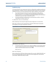
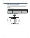
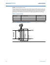
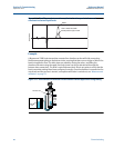
For the Rosemount 5300 Series in applications with rapid level changes, such as a flash tank,
measurement parameters can be adjusted to enable a faster response time. Select Rapid Level
Changes under Process Condition, and set Damping Value to 0 s (default value is 2 s).
RRM > Tank > Rapid Level Changes (Under Process Condition)
RRM > Advanced > Echo Tracking > Damping Value