


50
Reference Manual
00809-0700-4530, Rev AA
Section 3: Commissioning
September 2013
Commissioning
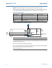
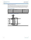
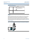
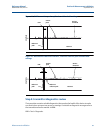
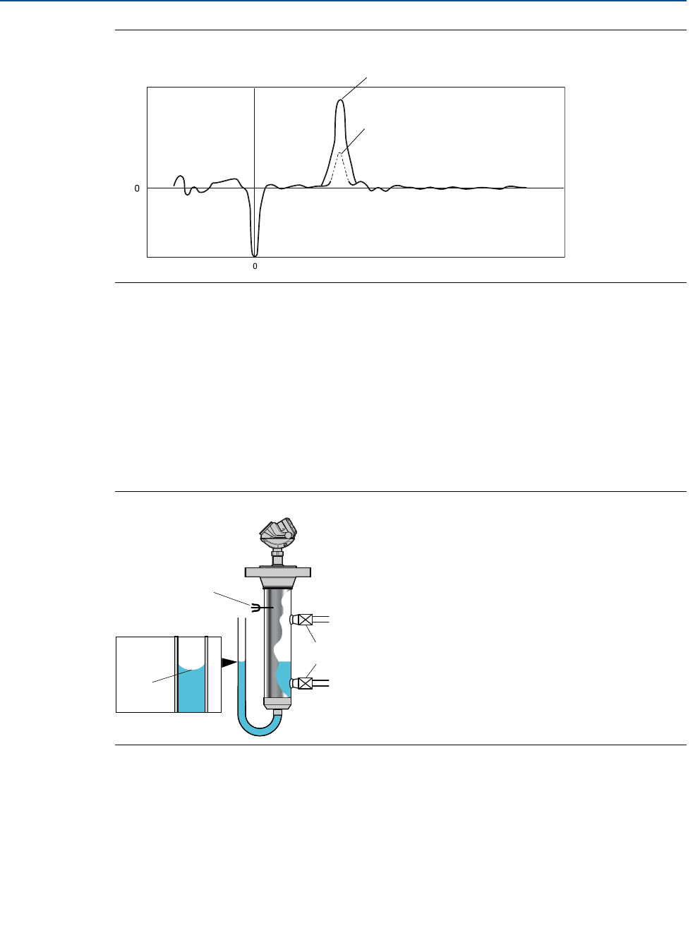
Figure 3-11. The difference between the amplitude of surface peaks in the case of
simulated and actual liquid levels
Example
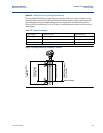
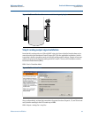
A Rosemount 5300 Series transmitter mounted in a chamber can be verified by connecting
flexible transparent tubing to the bottom drain, ensuring that there are no crimps or folds in the
bend to impede the flow. The inlet-pipes are sealed by closing the valves, and filling the
chamber with water using the upper vent hole (water can also be introduced through the
bottom drain connection). The level is varied between the 4-20 mA set-points to verify that the
basic transmitter settings have been configured correctly. Once the chamber is mounted on the
actual tank and the process is started, a complete verification is carried out, see “Measurement
validation” on page 51.
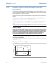
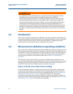
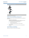
Figure 3-12. Verification of transmitter measurement in bridle application using tubing
Water
Distance
Amplitude
How it would look with
actual product (oil) in tank
Closed
Valves
Fill water here
Measure
here