


15
Reference Manual
00809-0700-4530, Rev AA
Section 2: Installation Considerations
September 2013
Installation considerations
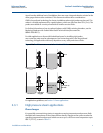
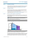
to center the probe. Chambers larger than 6 in. (150 mm) can be used, but provide no
advantages for the radar measurement
(1)
.
When specifying a chamber, it is also important to consider the physical weight of the
instrument and chamber, the properties of the liquid, and the chance of plugging due to the
build-up of deposits.
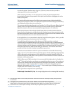
The location of the side-pipes and the effective measurement range is determined by the
mating tank connections. There are no diameter requirements for the side-pipes, but build-up
and clogging should be taken into consideration.
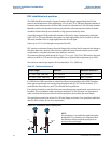
The recommended inlet pipe diameter is not less than 1 in. (25 mm) for water (filtered minimal
quality), lube oil, or liquids with similar viscosity. For fuel oil, bunker oil, that is liquids with
higher viscosity, the minimum recommended inlet pipe diameter is 2 in. (50 mm).
Note that the diameter of the inlet pipe should always be less than the chamber diameter.
Ensure that the inlet pipes do not protrude into the chamber because they may interfere with
the radar measurement. Always use the same material of construction for the chamber and the
tank or mechanical tensions can arise in the side-connections.
In hot applications, it is recommended to keep the length of the inlet pipes as short as possible
to minimize temperature drop between tank and chamber.
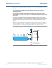
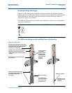
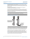
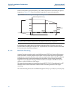
To simplify the verification process of the Rosemount GWR transmitters, venting is
recommended to manipulate the level in the cage and to drain the cage. A standard integral
cage vent located on the top part of the chamber (typical position is right below the flange), and
a drain at the bottom of the chamber, are suitable. Refer to the Rosemount 9901 Series Product
Data Sheet (Document No. 00813-0100-4601) for information. The vent and drain make it
possible to isolate the whole chamber during fill/drain procedures.
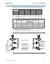
For the Rosemount 5300 Series with DVC special considerations to chamber dimensioning
apply. A 3 or 4-in. (75 or 100 mm)
(2)
inner diameter bypass chamber with flanges appropriately
sized for the pressure and temperature of the application is required. Materials used for the
chamber should meet ASME boiler code requirement and the chamber should be isolated from
the boiler or HP heater by valves.
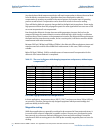
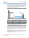
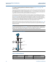
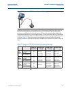
With the Rosemount GWR transmitters it is recommended that single probes in chambers be
used
(3)
. The single lead probe can tolerate any magnetite layer that may occur. The probe must
not touch the chamber wall and should extend the full height of the chamber, but should not
touch the bottom of the chamber. Allow for transition zones (varies with probe type and
dielectric of the media), see Table 2-5 on page 17. Also consider type of flushing connection to
simplify calibration verification, and cleaning.
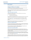
Probe type selection depends on the probe length:
Probe length is less than 3 ft (1 m): Use a single rigid probe and no centering disk is needed
(4)
.
(1) The single probe creates a virtual coaxial probe with the chamber as the outer tube which helps to amplify the signal returned
from the media.
(2) It is possible to use a chamber with a 2 in. (50 mm) inner diameter, but not recommended as best practice.
(3) The single probe creates a virtual coaxial probe with the chamber as the outer tube. The extra gain provided by the twin and
coaxial probes is not necessary; the electronics in the Rosemount 5300 Series is very sensitive and is not a limiting factor.
(4) The transition zones, and the height of the weight, limit the usage of single flexible probes shorter than 3 ft (1 m).