


69
Reference Manual
00809-0700-4530, Rev AA
Section 5: Troubleshooting Procedures
September 2013
Troubleshooting procedures
5.4.2 Rosemount GWR transmitter threshold settings
Recommendations for the Rosemount 3300 and 5300 Series:
1. Use the automatic threshold settings and ensure that the dielectric constants of the
vapor and products have been entered correctly
2. If needed, apply the Measure & Learn function
3. If needed, use the following best practices to apply custom threshold adjustments:
Generally, the threshold should be at 40-50% of the surface peak. Example: If the
surface is 2000 mV, the threshold should be set at 800-1000 mV
It should never be closer than 300 mV to any disturbing objects. Example: If there
is a 1100 mV peak from an inlet-pipe, the threshold around it should be 1400 mV
The threshold should never be below 800 mV in the range 0-1 ft (0.3 m) and
never below 500 mV from 1 ft (0.3 m) upwards
For products with very low dielectric constants, such as solids, it may be required to lower the
threshold additionally, and/or to activate the PEP function. See “Probe End Projection
(Rosemount 5300 Series solids measurement)” on page 48 for the activation of PEP.
5.4.3 Rosemount non-contacting radar transmitter threshold
settings
Recommendations for the Rosemount 5400 and 5600 Series:
1. Apply the Measure & Learn function (Rosemount 5400 Series only)
2. If needed, use the following best practices to apply custom threshold adjustments:
Generally, the threshold should be at 20% of the surface peak.
Example: if the surface is 2000 mV, the threshold should be set at 400 mV
It should never be closer than 200 mV to any disturbing objects.
Example: if there is a 500 mV peak from an obstacle, the threshold around it
should be 700 mV
The threshold should never be below 300 mV
For products with very low dielectric constants, such as solids, it may be required to lower the
threshold additionally. For the Rosemount 5600 Series, manual adjustments are always
recommended.
5.4.4 Common problems
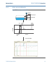
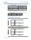
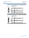
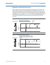
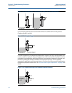
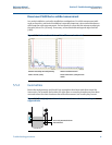
Threshold below the surface peak
In this example, the threshold has incorrectly been set above the surface peak, see Figure 5-7.
The problem can be corrected by lowering the threshold, see Figure 5-8.