


45
Reference Manual
00809-0700-4530, Rev AA
Section 3: Commissioning
September 2013
Commissioning
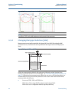
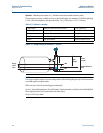
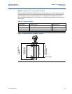
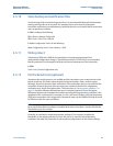
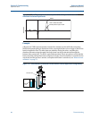
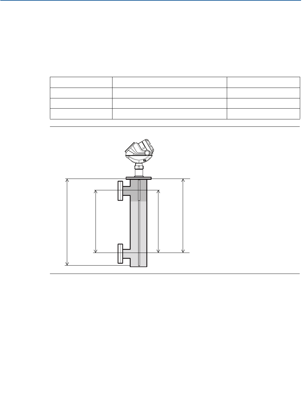
Option 2 - Setting LRV to 0 in. (0 mm) at the lower tap
The tank height should be set to the distance to the zero level point. In this example, it is the
lower side-pipe, located 19 in. (483 mm) below the reference point. Output range values will
equal the pipe connection heights relative to the zero level point. LRV should be set at 0 in.
(0 mm), the URV should be set at 14 in. (356 mm), and the probe should be set to the correct
probe length.
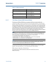
Table 3-6. Option 2 example:
Figure 3-8. Range values for chambers - option 2
Gauge height distance to LRV 19 in. (483 mm)
Probe length probe length 23 in. (584 mm)
URV distance between connections 14 in. (356 mm)
LRV center of bottom connection 0 in. (0 mm)
Probe length 23 in.
(584 mm)
Displacer length
14 in. (356 mm)
LRV 0 in. (0 mm)
URV 14 in. (356 mm)
Tank Height
(reference gauge height)
19 in. (483 mm)