


71
Reference Manual
00809-0700-4530, Rev AA
Section 5: Troubleshooting Procedures
September 2013
Troubleshooting procedures
Disturbance misinterpreted as level
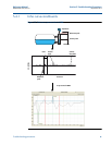
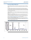
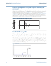
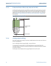
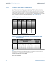
In this example, the transmitter incorrectly identifies the reflection from an inlet-pipe as the
product surface, because it is the first peak above the surface threshold, see Figure 5-9. Tall,
narrow, and/or rough nozzles can also create disturbance echo in the form of double bounces.
The double bounce will always appear at twice the disturbance distance. Ensure that the recom-
mendations in Section 2: Installation considerations are followed. The problem can be solved by
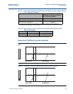
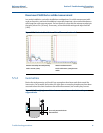
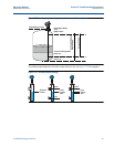
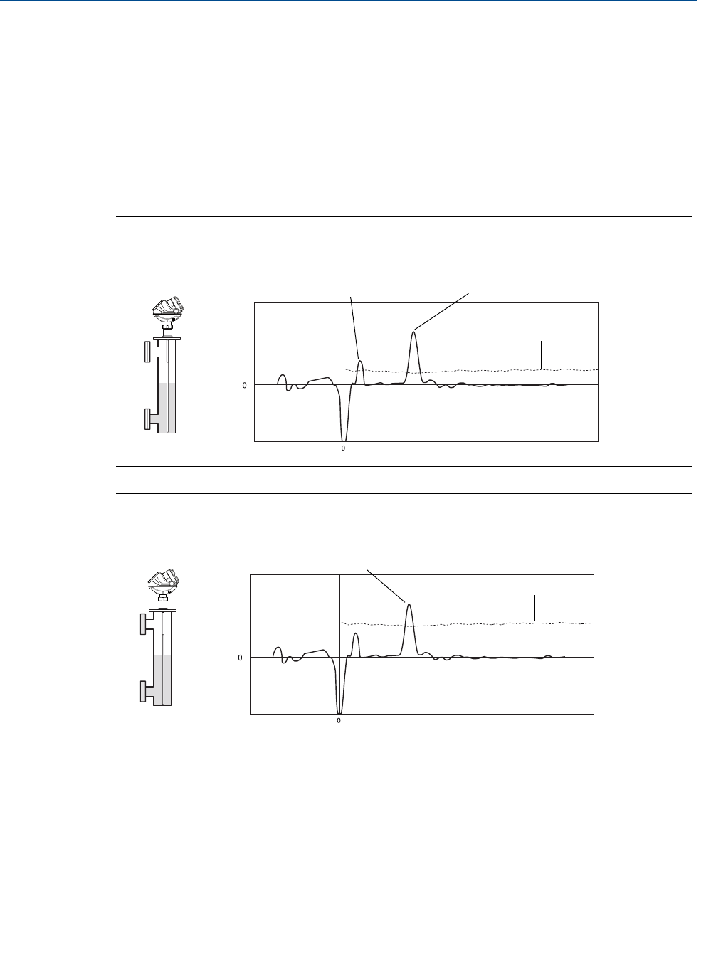
increasing the surface threshold (see Figure 5-10) or, in some cases where the disturbance is
close to the transmitter flange, by increasing the UNZ or performing the 'Near Zone Trim'
command.
Figure 5-9. The surface is the reflection from the inlet-pipe
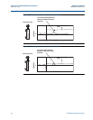
Figure 5-10. Surface peak identified correctly
Amplitude
Distance
Rosemount 5301
Actual
level
The reflection from the inlet-pipe is
selected as the surface because it is the
first peak above the surface threshold.
Surface threshold
(ATC)
Amplitude
Distance
Rosemount 5301
Surface threshold
(ATC)
The peak from the actual level is now correctly
identified; it is the first peak above the surface
threshold.