


12
Reference Manual
00809-0700-4530, Rev AA
Section 2: Installation Considerations
September 2013
Installation considerations
DVC installation best practices
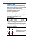
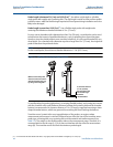
The GWR should be mounted in a bypass chamber with flanges appropriately sized for the
pressure and temperature of the application. A 3 or 4 inch (75 or 100 mm) diameter chamber is
recommended as best practice, but the GWR can also be mounted in a 2 inch (50 mm) chamber.
Materials used for the chamber should meet local boiler code requirements and the chamber
should be isolated directly from the boiler or high pressure heater by valves.
A specially designed HTHP probe with reference reflector for vapor compensation should be
used. For 2 in. (50 mm) chambers, this probe is a single rigid probe, and for 3 and 4 in. (50 and
100 mm) chambers this is a single rigid probe with an outer pipe.
Probes up to 13.1 ft. (4 m) length are supported for DVC.
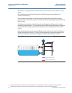
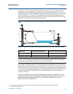
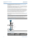
DVC requires a minimum distance from the flange to the surface level to measure the change in
the vapor dielectric constant. If the level rises within this area, the unit switches over to static
compensation, using the last known vapor dielectric constant.
This minimum distance (indicated by X in Figure 2-9 on page 18) is 22 in. (560 mm) for the short
reflector, and 28 in. (710 mm) for the long reflector, to dynamically compensate up to 100%.
The minimum measuring range for this functionality is 12 in. (300 mm).
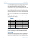
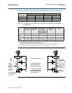
Table 2-2. Minimum distance X
If a 5300 Series GWR transmitter is ordered from Rosemount together with a 9901 Chamber,
these space requirements are met by using the option code G1 or G2 for the chamber. G1 is
used with the short reflector, and G2 is used with the long reflector.
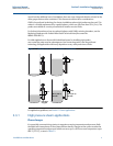
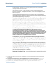
If an existing chamber is used which does not meet these space requirements, a spool piece can
be added. For an installation with a spool piece with the 2 in. DVC solution, it is important to
make sure that the reference reflector and the spool piece do not have the same length.
The spool piece needs to be at least 2 in. (50 mm) longer or shorter. For a spool piece with the 3
and 4 in. DVC solution, this is not a requirement.
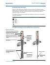
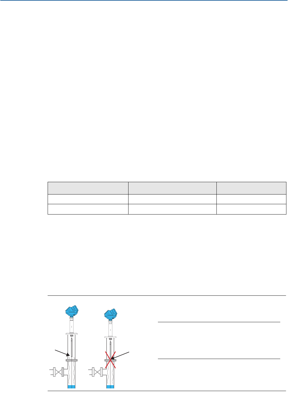
Figure 2-5. Installation with a spool piece
Probe length Reflector Minimum distance X
35 - 158 in. (900 - 4000 mm) 14 in. (350 mm) 22 in. (560 mm)
43 - 158 in. (1100 - 4000 mm) 20 in. (500 mm) 28 in. (710 mm)
Not OK
OK
NOTE:
If a spool piece is used with the single lead probe
designed for 2 in. chambers, it is important that
the reference reflector and the spool piece do
not have the same length.