


10
Reference Manual
00809-0700-4530, Rev AA
Section 2: Installation Considerations
September 2013
Installation considerations
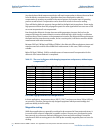
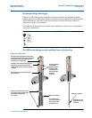
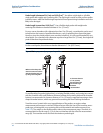
DVC requires a special probe with a built-in reflector for measurement of the dielectric of the
steam.
DVC works by using a target at a fixed distance. With this target, the vapor dielectric is
measured continuously.
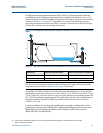
The transmitter knows where the reflector pulse should have been if there were no vapor
present. However, since there is vapor in the tank, the reflector pulse appears beyond the actual
reflector point.
The distance between the actual reflector point and the apparent reflector point is used to
calculate the vapor dielectric. The calculated dielectric is then dynamically used to compensate
for vapor dielectric changes and eliminates the need to do any compensation in the control
system.
When the distance between the mounting flange and the surface is less than 22 in. (560 mm)
for the short reflector, and 28 in. (710 mm) for the long reflector, the function switches from
dynamic to static vapor compensation using the last known vapor dielectric constant.
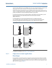
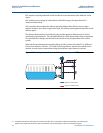
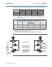
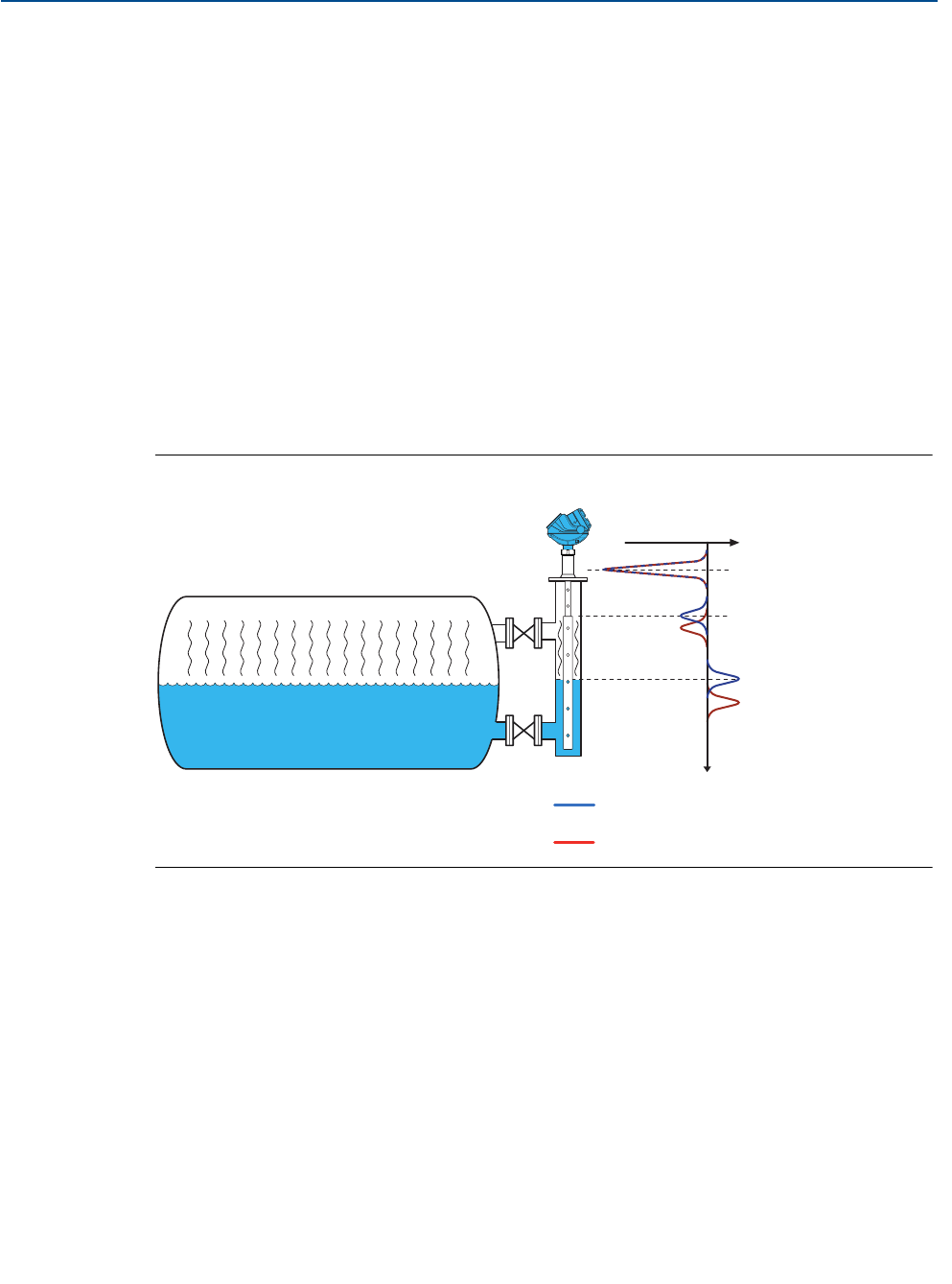
Figure 2-2. Radar signal curve before and after vapor compensation
(1)
(1) The figure illustrates the radar signal curve before and after vapor compensation. Without compensation, the surface pulse
appears to be beyond the actual level. After compensation, the surface appears at the correct surface level point.
Signal curve before DVC
Signal curve after DVC