


14
Reference Manual
00809-0700-4530, Rev AA
Section 2: Installation Considerations
September 2013
Installation considerations
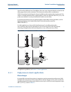
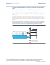
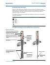
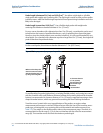
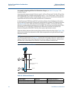
How to choose reflector length
The long reflector, 20 in. (500 mm), has the best accuracy and is recommended for all chambers
where the dimensions of the chamber allow for it.
If the distance from the flange to the upper inlet is less than 28 in. (710 mm), the short reflector
should be chosen.
This distance is a minimum when dynamic compensation is required within the whole
measuring range from the lower to the upper inlet. If this is not required, the long reflector can
be used and dynamic compensation is possible up to 28 in. (710 mm) from the flange.
However, always ensure that there are no disturbances from inlets etc close to the reference
reflector end when using the 2 in. DVC solution.
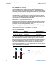
DVC calibration
When a transmitter is ordered with the optional DVC, the function is activated from factory and
the special probe is supplied. For the 2 in. solution, a calibration procedure is needed on-site
during the commissioning phase. For the 3 and 4 in. solution, the transmitter is calibrated from
factory and no calibration on-site is normally needed. There are, however, two cases where a
calibration procedure is needed for the 3 and 4 in. solution; if the transmitter is reset to factory
settings which will delete the DVC calibration, or if a different transmitter head is mounted on
the DVC probe.
If a calibration procedure is needed, this should be performed with an empty chamber at
ambient conditions.
For best performance, it is recommended that the chamber is cleared of any steam and/or
condensate prior to the calibration. See the Reference Manual supplied with the transmitter for
details on the calibration procedure.
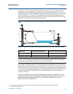
Note that Probe End Projection and Signal Quality Metrics are disabled when DVC is enabled. To
minimize errors due to installation, it is recommended that:
the distance between the chamber and the vessel be kept as short as possible
connections to the chambers should be large enough to allow good fluid flow through
the chamber and the piping to it should be well insulated so the fluid temperature is as
close as possible to the vessel temperature
For further information on chamber insulation, see “Insulation” on page 22.
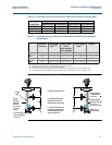
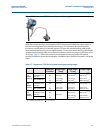
2.3.2 Chamber fabrication and probe selection
Dimensioning the chamber correctly and selecting the appropriate probe is key to success in
guided wave radar applications. Either follow the recommendations below and have the
chamber manufactured accordingly, or purchase the Rosemount 3300 or 5300 Series
transmitter bundled with the Rosemount 9901 Chamber where Emerson has already
incorporated these best practices. See the Rosemount 9901 Chamber for Process Level Instru-
mentation Product Data Sheet (Document No. 00813-0100-4601) for a 9901 model code
example.
The recommended chamber diameter is 3 in. (75 mm) or 4 in. (100 mm). Chambers with a
diameter less than 3 in. (75 mm) may cause problems with build-up and it may also be difficult