


54
Reference Manual
00809-0700-4530, Rev AA
Section 4: Measurement validation
September 2013
Measurement validation
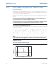
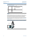
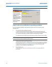
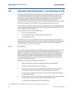
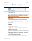
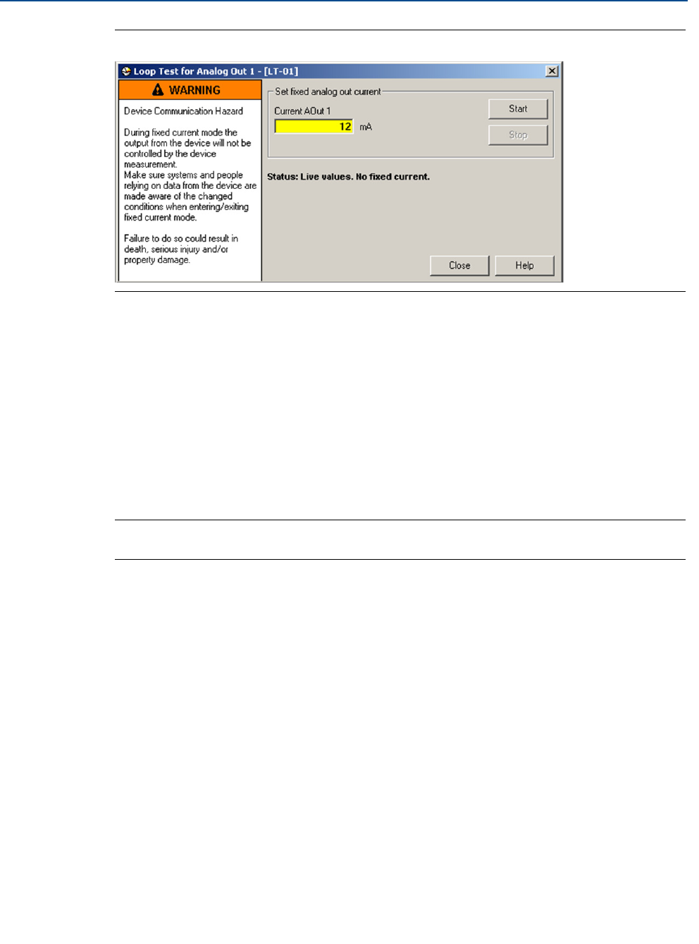
Figure 4-3. Loop test for Analog Out 1
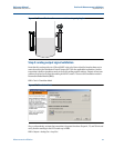
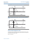
Step 3: echo-curve verification at operating conditions
At normal operating conditions, download and review the echo-curve according to the
following steps:
1. Check reference pulse amplitude and position
Compare the result against the previous plots, taken during commissioning, and
previous verification rounds. Note that deviation of pulse amplitude and position may
occur between plots taken at ambient conditions and operating conditions.
For a Rosemount 5301 with DVC also verify that the reference reflector echo is visible.
NOTE:
The non-contacting radar has a positive reference pulse.
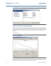
2. Review peak amplitudes and threshold settings
Verify that the surface peak is visible and that the thresholds have been set according to
the best practices in Section 5: Troubleshooting procedures. If possible, compare the
current echo-curve with previously stored echo-curves taken during operating
conditions. There should be no major differences.
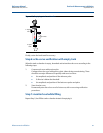
3. Store the echo-curve
Permanently store the echo-curve for future use, with re-occurring verification
procedures.