


18
Reference Manual
00809-0700-4530, Rev AA
Section 2: Installation Considerations
September 2013
Installation considerations
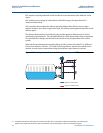
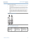
An example using the guidelines for fabrication of cages (see Table 2-5 on page 17 for
transition zones).
Assuming level measurement of oil (worst-case): A > 6.3 in. (16 cm) and C > 9.8 in. (25 cm) for a
rigid single probe with a metallic centering disk, and A > 7.1 in. (18 cm) and C > 9.4 in. (24 cm)
for a single flexible probe with a standard weight. There is a 2 in. (5 cm) clearance between the
cage bottom and the end of the probe included in the C-dimensions.
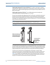
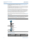
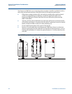
For the Rosemount 5300 Series with DVC a minimum distance from the flange to the surface
level is required to measure the change in the vapor dielectric constant. This minimum distance
(X in Figure 2-9) is 22 in. (560 mm) for the short reflector, and 28 in. (710 mm) for the long
reflector, to dynamically compensate up to level 100%. The minimum measuring range for this
functionality is 12 in. (300 mm). If a Rosemount 5300 Series transmitter is ordered from
Rosemount together with a 9901 Chamber, these space requirements are met.
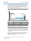
When the distance between the mounting flange and the surface is less than X (see Figure 2-9),
the function switches from dynamic to static vapor compensation using the last known vapor
dielectric constant.
NOTE:
The distance requirements (X in Figure 2-9) stated above only apply if dynamic compensation is
required within the whole measuring range from lower to upper inlet. However, always ensure
that there are no disturbances from inlets etc. close to the reference reflector end.
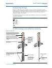
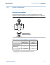
Figure 2-9. DVC minimum distance
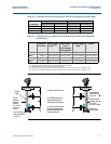
Table 2-6. Minimum distance X
Probe Length Reflector Minimum Distance X
35 - 158 in. (900 - 4000 mm) 14 in. (350 mm) 22 in. (560 mm)
43 - 158 in. (1100 - 4000 mm) 20 in. (500 mm) 28 in. (710 mm)
Level: 100%
Level: 0%
X
Minimum measuring range:
12 in. (300 mm)