


9
Reference Manual
00809-0700-4530, Rev AA
Section 2: Installation Considerations
September 2013
Installation considerations
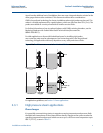
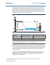
Heavy vibrations
Heavy vibrations from pumps can cause a noisy signal from mechanical-based techniques.
Advantages of GWR over other techniques
Since GWR measurement devices are completely independent of density, these associated
errors are not present, thus eliminating the need for this compensation.
GWR has no moving parts that can freeze or stick from magnetite coating or cause noisy signal
due to vibration. Therefore, GWR offers additional advantages of lower maintenance and
greater stability.
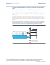
Vapor compensation functionality
In the Rosemount 5300 Series Superior Performance GWR, there are two functions to
compensate for the vapor dielectric:
Static Vapor Compensation (SVC)
Dynamic Vapor Compensation (DVC)
With either option, the compensation occurs in the transmitter electronics and a corrected level
measurement is provided to the control system. No additional compensation is required.
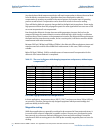
As it can be seen in Table 2-1, at 247 psia (17 bar), there is an error in distance of 3.4%. At
1543 psia (106 bar), there is an error of 20.9% when there is no compensation for the vapor
dielectric.
The error in distance increases with the pressure, and at some point this deviation is not
negligible and must be taken into account in order to get high accuracy.
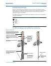
Static vapor compensation (SVC)
For the static compensation function, the dielectric of the vapor at expected operating pressure
and temperature is manually entered as part of the configuration of the transmitter. This allows
the unit to compensate for the dielectric at operating conditions.
The static compensation works well under stable conditions and in these applications, the
standard High Temperature/High Pressure (HTHP) probe is used.
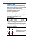
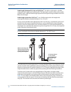
Dynamic vapor compensation (DVC)
DVC becomes more important for the higher pressure applications which may have more
variations in the operating conditions or where the users want to be able to verify the unit under
near ambient conditions, such as during startup and shutdown, without having to modify the
vapor dielectric settings.
Vapor dielectric does not affect the measurement accuracy until the pressure is higher than
145 psia (10 bar). DVC should be considered when the pressure is above 247 psia (17 bar) when
the error is more than 2%, see Table 2-3 on page 13. In these cases, DVC can bring the error back
to 2%, or in some conditions even down to 1%.
Application and installation conditions, such as lower temperature in the bypass chamber, can
cause changes within the measured media. Therefore, the error readings can vary depending on
the application conditions and may cause an increase of the measuring error by a factor of 2 to
3.