


Copernicus GPS Receiver 79
MECHANICAL SPECIFICATIONS 7
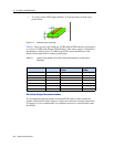
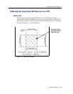
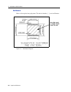
Soldering the Copernicus GPS Receiver to a PCB
Solder mask
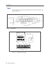
When soldering the Copernicus GPS Receiver to a PCB, keep an open cavity
underneath the Copernicus module (i.e., do not place copper traces or solder mask
underneath the module). The diagram below illustrates the required user solder mask.
The units in brackets, [ ], are in millimeters.
Figure 7.3 Solder Mask Diagram
No solder mask
or copper traces
under the unit.