


5 APPLICATION CIRCUITS
62 Copernicus GPS Receiver
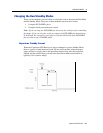
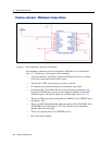
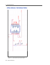
Passive antenna—Minimum Connections
Figure 5.1 Passive Antenna - Minimum Connections
The minimum connection set for the Copernicus GPS Receiver is illustrated in
Figure 5.1. Following is a description of the schematic.
• A passive antenna is used. The Copernicus GPS Receiver has an on-board
LNA and an Automatic Gain Control circuit.
• The Pin LNA_XEN is not necessary and not connected.
• No Antenna open and short detection or protection is provided.
• If the Open (Pin 7) and Short (Pin 8) are kept unconnected (floating), the
Copernicus GPS Receiver reports an open antenna condition. If a normal
condition report is desired, tie Open low and Short high. (See Table 3.2).
• There is no HW reset ability through the pin XRESET, since XRESET pin is
tied High to VCC.
• There is no HW initiated Standby Mode through the Pin XSTANDBY, since
XSTANDBY pin is tied High to VCC. The software serial command to
Standby Mode will still apply.
• There is no separate power for STANDBY power.
• One serial port is utilized.
IMAGE TO COME