


Copernicus GPS Receiver 11
STARTER KIT 1
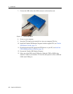
Interface Connections
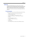
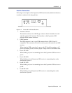
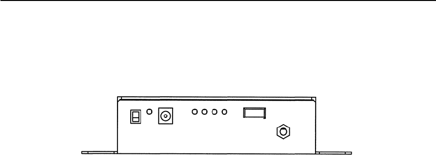
Following is a description of the Copernicus GPS interface unit (numbered references
correlate to numbers in the image below).
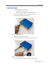
Figure 1.4 Front side of the Interface Unit
1. Antenna Connector
The antenna connector is an MCX type connector that is intended to be used
with the supplied 3.0V antenna. This interfaces to the Copernicus GPS
reference board antenna connector.
2. USB Connector
The USB connector is an A-type USB connector that is USB 2.0 and 1.1
compatible. This connection can also be used to power the starter kit and GPS
receiver.
When using the USB connection for power, the PC should be running on AC
power (not battery power) to ensure proper voltage levels to the interface unit.
3. Port A-TX LED
When blinking red, user is transmitting data to the Copernicus GPS receiver on
port A.
4. Port A-RX LED
When blinking red, the Copernicus GPS receiver is transmitting data to the
user device on port A.
5. Port B-TX LED
When blinking red, user is transmitting data to the Copernicus GPS receiver on
port B.
6. Port B-RX LED
When blinking red, the Copernicus GPS receiver is transmitting data to the
user device on port B.
8
6 5 4 3
2
1
9
7