


Copernicus GPS Receiver 63
APPLICATION CIRCUITS 5
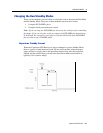
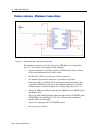
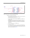
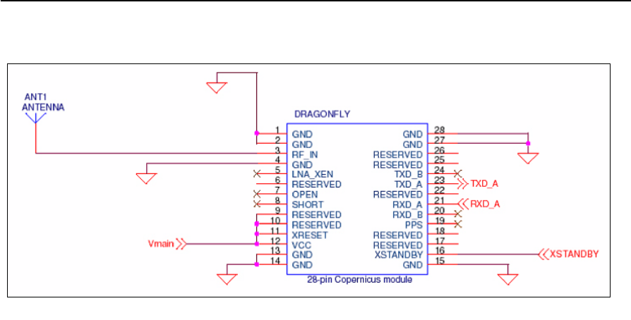
Figure 5.2 Passive antenna - HW Activated Standby Mode Available
Following is a description of the schematic:
• Passive Antenna is used. The Copernicus GPS Receiver has an on-board LNA
and an Automatic Gain Control circuit.
• The Pin LNA_XEN is not necessary and not connected.
• There is no HW reset ability through the pin XRESET, since XRESET pin is
tied High to VCC.
• HW initiated Standby Mode through the Pin XSTANDBY is possible, since
XSTANDBY pin is not tied High to VCC. The software serial command to
Standby Mode can still be used as a second method to force the module into
Standby Mode.
• There is no separate power for STANDBY power.
• One serial port is utilized.
• No Antenna open and short detection or protection is provided. When Open
(Pin 7) and Short (Pin 8) are kept unconnected (floating), the Copernicus GPS
Receiver reports an open antenna condition. If a normal condition is desired, tie
Open Low and Short High. See Table 3.2.