


1 STARTER KIT
12 Copernicus GPS Receiver
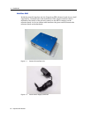
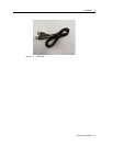
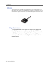
7. Power Connector
The power connector (barrel connector) is located on the front right side of the
starter kit. The power connector connects to the AC/DC power converter
supplied with the starter kit. The power converter converts 100 -240 VAC To
12 or 24VDC. The power connector can accept 9 to 32 VDC.
8. Power LED
The Power LED indicates when main power, VCC, is available to the receiver.
Main power is controlled by the Power Switch (#8). When the switch is in the
ON position the LED illuminates Green and VCC is supplied to the receiver.
When the switch is in the OFF position the LED is not lit and the receiver is
powered only by the standby regulator or battery.
Note – For the Copernicus GPS receiver to operate with standby power, the power
source must be from the main power connector (#6) (not from the USB connector).
9. Power Switch
The power switch is used to enable or disable VCC to the receiver.
10. PPS BNC (located on the backside of the interface unit)
The BNC connector provides a 5V TTL level PPS pulse output by the receiver.
The output configuration is controlled by the receiver, not the starter kit driver
circuit. This output is able to drive a 50ohm load.
Note – The Copernicus GPS receiver reference board contains a number of
configuration jumpers for use with various Trimble GPS receivers. Jumpers JP5 and
JP15 must be in place for use with Copernicus GPS receiver.