


5 APPLICATION CIRCUITS
64 Copernicus GPS Receiver
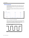
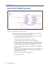
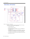
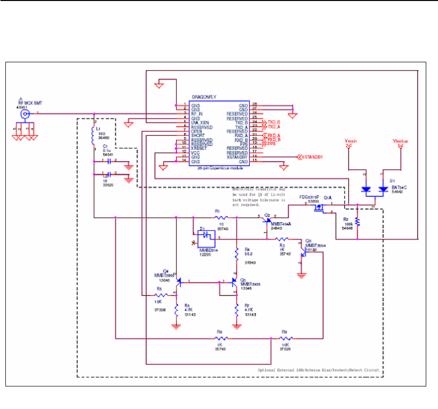
Active Antenna—Full Connection
Figure 5.3 Active antenna - Full connection
Following is a description of the schematic with antenna detection, when using a
second source to power the unit when in Standby Mode.
• An active antenna is used.
• The Pin LNA_XEN is connected.
• HW reset ability through the pin XRESET is possible, since XRESET pin is
not tied High to VCC.
• HW initiated Standby Mode through the Pin XSTANDBY is possible, since
XSTANDBY pin is not tied High to VCC. Serial Command to Standby Mode
can still apply as the second method to force the module to Standby Mode.
• A second power source for the standby voltage is applied (see the note below).
• Both serial ports are utilized.