


Copernicus GPS Receiver 43
INTERFACE CHARACTERISTICS 3
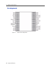
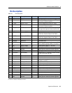
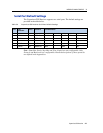
Pin Description
Table 3.1 Pin Description
G: Ground; I: Input; O: Output; P: Power
Pin Name Description Function Note
1 GND Ground G Signal ground. Connect to common ground.
2 GND RF Ground G One of two RF grounds adjacent to RF input.
Connect to RF ground system.
3 RF Input GPS RF input I 50-ohm unbalanced (coaxial) RF input.
4 GND RF Ground G One of two RF grounds adjacent to RF input.
Connect to RF ground system.
5 LNA_XEN LNA Enable O Can be used with active antennas only. Active
low logic level signal to control external LNA.
6 Reserved Reserved I/O Do not connect.
7 OPEN Antenna OPEN I Logic level from external antenna detection
circuit. See “Antenna Detect Truth Table”.
8 SHORT Antenna SHORT I Logic level from external antenna detection
circuit. See “Antenna Detect Truth Table”.
9 Reserved Reserved I Connect to VCC.
10 Reserved Reserved I Connect to VCC.
11 XRESET Reset I Active low logic level reset. Connect to VCC
with or without a pullup resistor, if not used.
12 VCC Supply voltage P Module power supply 2.7 - 3.3 VDC
13 GND Ground G Signal ground. Connect to common ground.
14 GND Ground G Signal ground. Connect to common ground.
15 GND Ground G Signal ground. Connect to common ground.
16 XSTANDBY Run/Standby I Selects “RUN” or “STANDBY” mode. Connect
to VCC if not used (run only).
17 Reserved Reserved I/O Do not connect.
18 Reserved Reserved I/O Do not connect.
19 PPS Pulse per second O Logic level timing signal at 1 Hz. Do not
connect if not used.
20 RXD_B Serial port B receive I Logic level secondary serial port receive.
21 RXD_A Serial port A receive I Logic level primary serial port receive.
22 Reserved Reserved I/O Do not connect.
23 TXD_A Serial port A transmit O Logic level primary serial port transmit.
24 TXD_B Serial port B transmit O Logic level secondary serial port transmit.
25 Reserved Reserved I/O Do not connect.
26 Reserved Reserved I/O Do not connect.
27 GND Ground G Signal ground. Connect to common ground.
28 GND Ground G Signal ground. Connect to common ground.