


Copernicus GPS Receiver 111
FIRMWARE UPGRADE 11
Error Recovery
The GPS receiver is designed in such way that the system will not be damaged during
a firmware update. When there is an unexpected error while loading firmware, the
target can always be restarted by cycling the main power. At power-up, the target will
automatically enter the monitor mode if the firmware loading process has not
completed successfully. In such a case, the host will able to repeat the firmware
loading procedure as described above.
If the Boot Code in the Flash memory is inadvertently overwritten, the module can
become unusable. See Warning at the end of the description of the Monitor Mode
Packet ID – 0x8B.
Monitor Interface Protocol
Protocol Format
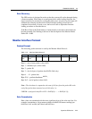
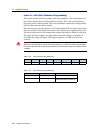
The following packet structure is used by the Monitor Mode Protocol:
Byte 0 – start of new packet (value: 0x02)
Byte 1 – delimiter byte (value: 0x00)
Byte 2 – packet ID
Byte 3 – size (in bytes) of packet data (DATA field only)
Bytes 4 … N – packet data
Byte N+1 – packet checksum
NOTE 1
.
Byte N+2 – end of packet (value: 0x03)
Note – The checksum is computed as the sum of all bytes from the packet ID to the
end of the packet data truncated to an 8-bit value, i.e.:
CHKSM = (unsigned char)(ID + LEN + DATA[0] + … + DATA[N-1]);
Data Transmission
Data values are transmitted with the most significant byte of the value sent first. For
example, transmitting a 4-byte memory address 0x004101F0 means sending byte
0x00 first, 0x41 second, 0x01 third, and 0xF0 last.
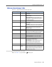
Table 11.2 Monitor Mode Protocol
BYTE 0 BYTE 1 BYTE 2 BYTE 3 BYTES 4 … N BYTE N+1 BYTE N+2
STX
0x02
NULL_C
0x00
ID LEN DATA CHKSM ETX
0x03