


Copernicus GPS Receiver 101
COPERNICUS REFERENCE BOARD 10
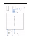
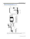
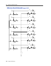
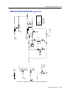
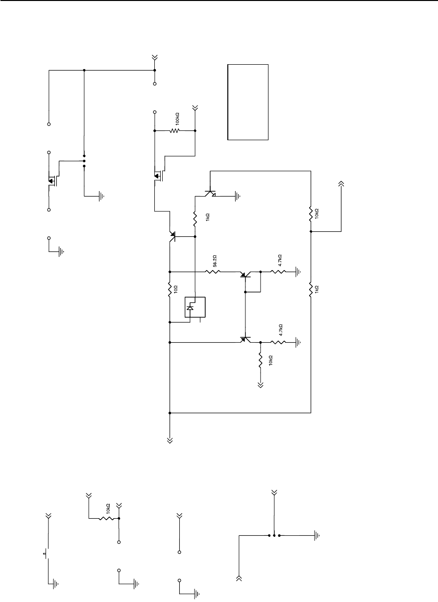
Reference Board Schematic (page 3 of 3)
Figure 10.3 Copernicus Reference Board Schematic (Page 3)
BOOT
MONITOR
XRESET
Vmain
LNA_XEN
Vant
SHRT
OPN
XSTANDBY
Vmain
Vmain
State OPN SHRT
OPEN 1 1
SHORT 0 0
OK 0 1
Undefined 1 0
MMBTA70LT1 transistor may
be used for Q8 if 12-volt
back voltage tolerance is
not required.
Low to reset
Low to FLASH
High to RUN
Must be
pulled high
to run (R25)
OPEN = FLASH
Low to start
in MONITOR
High for
NORMAL start
OPEN =
NORMAL start
High to RUN
Low to force
to STANDBY
OPEN = RUN
NOTE: OPEN and SHORT
signal logic is not valid
(indicates antenna short)
when Antenna Power jumper
is removed or LNA_XEN is
high.
BOOT
J25
1 2
J27
MONITOR
1 2
J24
Aux Cntl
1
2
3
SW1
RESET_SW
1 2
J26
Antenna Power
12
D7
MMBD914
1
3
2
R26
Q8
MMBT404A
1
2
3
R34
R28
Q7A
FDG6316P
1
2
6
Q10
MMBT3906
1
23
Q7B
FDG6316P
4
5
3
Q11
MMBT3906
1
23
R30
J28
3-pin header
1
2
3
R25
Q9
MMBT3904
1
2 3
J23
Aux Power
1
2
R33
R32
R31
R29
J22
Aux Output
1
2
R27