


Chapter 3 Visual User Interface
Receiver Status Screen Data
3-14 Operating and Programming Guide
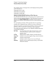
FFOM (Frequency Figure of Merit) indicates the stability of the
Receiver’s internal 10 MHz signal. The 10 MHz signal is controlled by
the SmartClock’s Phase-Locked Loop (PLL). Thus, the FFOM value is
determined by monitoring the status of the PLL.
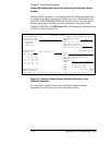
In the sample screen of Figure 3-6, the 0 indicates that the
SmartClock’s PLL is stabilized. The following table lists and defines
the FFOM values that could be displayed.
1PPS TI indicates the difference (timing shift) between the SmartClock
1 PPS and the internal GPS 1 PPS signals.
HOLD THR (holdover threshold) displays the user-entered time error
value.
ACQUISITION Section of the Status Screen
ACQUISITION Line
The ACQUISITION line in the screen summarizes the state of the
internal GPS Engine as indicated by the Tracking, Not Tracking, and
Position areas of the screen.
If the Receiver Engine was considered to be synchronized to the GPS
signal, the [GPS 1 PPS Valid] message will appear at the end of the
ACQUISITION line. If the Receiver has not yet synchronized to GPS,
the [GPS 1 PPS CLK Invalid] message will be displayed.
Tracking, Not Tracking
The Tracking table indicates the number of satellites the Receiver is
tracking.
The Not Tracking table indicates satellites predicted to be visible that
are not tracked, and all of the satellites that are assigned to a GPS
Engine channel but are not currently tracked.
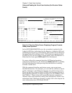
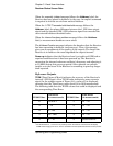
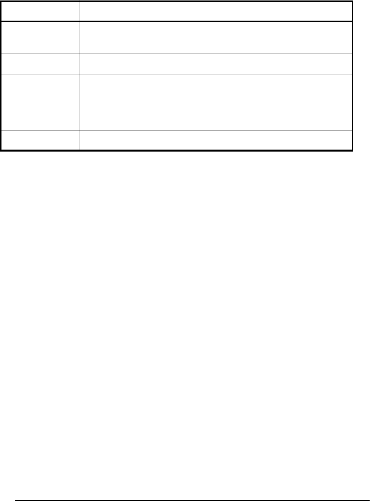
FFOM Value Definition
0 PLL stabilized — internal 10 MHz signal within
specification.
1 PLL stabilizing
2 PLL unlocked (holdover) — Initially the 10 MHz signal
will be within specifications. However, when in holdover,
the 10 MHz signal will eventually drift out of
specification.
3 PLL unlocked (not in holdover) — Do not use the output.