


Appendix D Performance Tests
Operational Verification
Operating and Programming Guide D-7
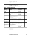
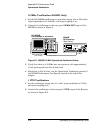
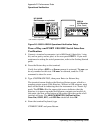
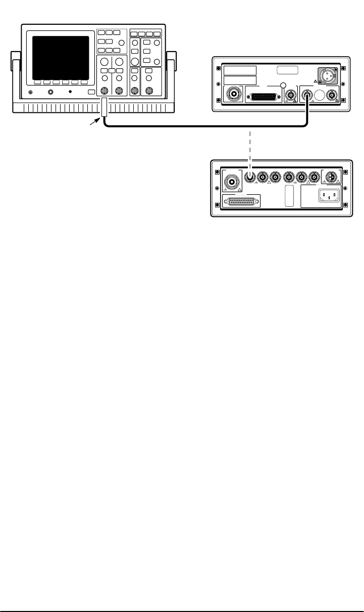
Figure D-2. 1 PPS Operational Verification Setup
3 Verify the presence of a TTL level pulse with approximately 20
µs pulse
width.
4 Mark Pass or Fail in Line 2 on the Operational Verification portion of
the appropriate ( 58503B or 59551A) Performance Test Record, located
at the end of this chapter.
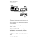
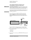
IRIG-B Verification (59551A Only)
1 Set the oscilloscope sweep rate to 1 msec/div and input amplitude to
5 Volts/div, dc-coupled.
2 Connect the oscilloscope to the rear-panel IRIG-B output of the 59551A
GPS Receiver as shown in Figure 2.
Verify that the display shows a sine wave with a period of 1 ms,
changing in amplitude from 5 Volts peak-to-peak, to greater than
10 Volts peak-to-peak. This is the IRIG-B time code modulating a
1 kHz carrier.
3 Mark Pass or Fail in Line 3 on the Operational Verification portion of
the 59551A Performance Test Record, located at the end of this
chapter.
HP 54600B
Oscilloscope or equivalent
58503B
GPS Receiver
1PPS
50
Ω Feedthrough
(HP 10100C)
BNC Cable
(Rear Panel)
!
! !
!
OR
59551A
GPS Receiver
(Rear Panel)
1PPS
!
!
ANT
!