


Chapter 2 Serial Interface Capabilities
Connecting a Computer or Modem
2-8 Operating and Programming Guide
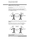
Making Your Own Cables
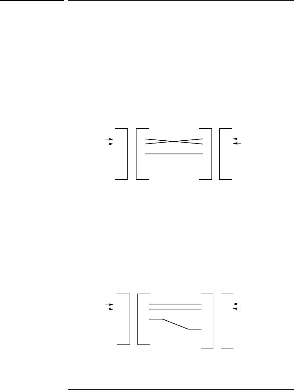
If you choose to make your own cable, see Figure Figure 2-3 and
Figure Figure 2-4.
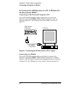
Figure Figure 2-3 illustrates how to make a DE-9S-to-DE-9P, DTE-
to-DCE interface cable that can replace the cable and adapter
combination of the HP 24542U cable and the HP 5181-6639 adapter for
use with PORT 2 of the 59551A.
Figure 2-3 DE-9S-to-DE-9P (DTE-to-DCE) Serial Interface Connection
to PORT 2
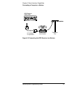
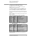
Figure Figure 2-4 illustrates how to make a DE-9S-to-DB-25P,
DTE-to-DTE interface cable that can replace the HP 24542G cable
(25-pin male to 9-pin female connectors) for use with PORT 1.
Figure 2-4 DE-9S-to-DB-25P (DTE-to-DTE) Serial Interface
Connection to PORT 1
11
22
33
44
55
66
77
88
99
PC
RS-232C (9-pin)
RX
TX
PC input
PC output
GND
DE-9P
Male
59551A PORT 2
RS-232C (9-pin)
DE-9S
Female
DE-9S-to-DE-9P
(DTE-to-DCE) Interface Cable
Data
Terminal
Equipment
Data
Communications
Equipment
DE-9S
Female
DE-9P
Male
RX
TX
GND
Instrument input
Instrument output
1
2
2
3
3
4
4
5
5
6
6
7
7
8
8
9
20
PC
RS-232C (9-pin)
RX
TX
PC input
PC output
GND
DE-9P
Male
DE-9S
Female
PORT 1
RS-232C (25-pin)
TX
DB-25P
Male
DB-25S
Female
DE-9S-to-DB-25P
(DTE-to-DTE)
Interface cable
Instrument output
Instrument input
Data
Terminal
Equipment
Data
Terminal
Equipment
1
22
RX
GND