


Appendix D Performance Tests
Complete Performance Tests
D-20 Operating and Programming Guide
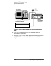
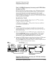
4 Connect the rear-panel 1 PPS from Receiver under test to Channel 1 of
the Universal Counter.
5 Connect the 1 PPS from the reference standard (5071A) to Channel 2.
6 On the terminal or computer, enter the following command to clear all
entries in the Diagnostic (status) Log:
:DIAG:LOG:CLEAR and press the Enter (or Return) key.
7 Set the Universal Counter function to take 100 samples of Time
Interval and compute the Mean value. Ensure that the inputs are set
to DC-coupled, 50 Ohms, and rising edge. Set the trigger level for both
inputs to 1Volt dc.
8 Record the average time interval for later comparison.
_______________________________________ seconds.
9 Disconnect the reference 1 PPS from input 2 and set the counter to
“COMMON” mode so the 1 PPS from the Receiver is input to both
channels. For this step, be sure the trigger levels are both set to 1 Volt
dc.
10 Set the counter to compute the Standard Deviation for the same 100
samples.
This is the RMS Jitter of the 1 PPS.