


Page 114 9 — Installation and Interfacing
9 — Installation and Interfacing9 — Installation and Interfacing
9 — Installation and Interfacing Rev. D
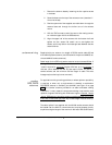
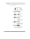
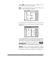
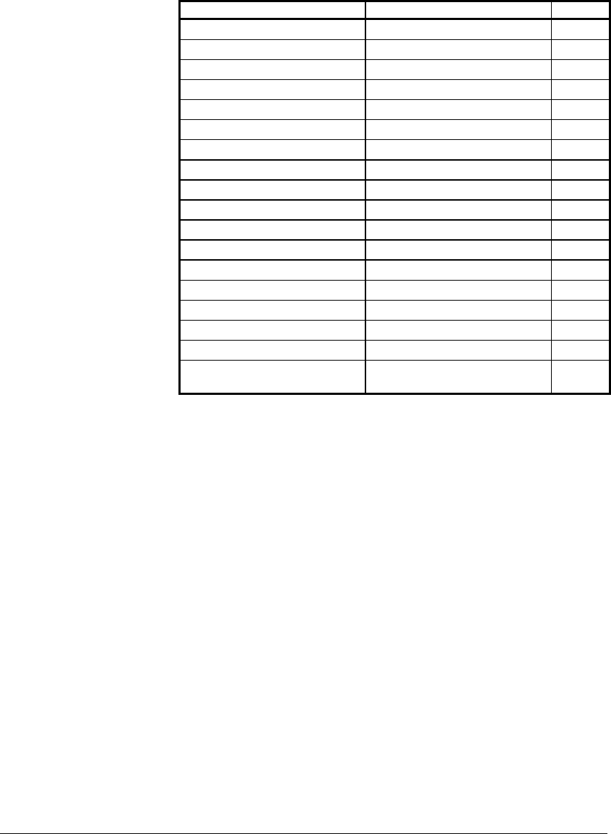
Description Wire Color Pin
NMEA PORT 1 INPUT A BROWN 3
NMEA PORT 1 INPUT B BLUE 1
NMEA PORT 1 INPUT GROUND WHITE w/BLUE STRIPE 4
NMEA PORT 1 OUTPUT A VIOLET 12
NMEA PORT 1 OUTPUT B GRAY 7
NMEA PORT 1 OUTPUT GND BLUE w/WHITE STRIPE 8
NMEA PORT 2 INPUT A WHITE w/BROWN STRIPE 6
NMEA PORT 2 INPUT B BROWN w/WHITE STRIPE 2
NMEA PORT 2 INPUT GROUND WHITE 5
NMEA PORT 2 OUTPUT A YELLOW 15
NMEA PORT 2 OUTPUT B ORANGE 11
NMEA PORT 2 OUTPUT GND BLACK 10
RS-232 GROUND TAN 17
RS-232 INPUT GREEN 16
RS-232 OUTPUT RED 18
EXT. GND / FOIL DRAIN WHITE/ORANGE & SHIELD 9
EXTERNAL SAVE IN ORANGE w/WHITE STRIPE 13
200 PPNM OUT
(Pulses Per Nautical Mile)
PINK 14
Table 2—Interface Connector Pins
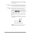
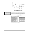
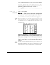
The Northstar 941X provides an open-collector transistor output (on pin
14) which is programmed to produce 200 pulses per nautical mile for
those devices requiring this output.
The emitter of the NPN transistor is connected to ground, and the col-
lector connects to the output pin side (see block diagram in Figure 12 on
page 115). The output can sink 100mA and can withstand a maximum
positive voltage of 50 volts.
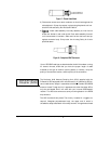
If the output connects to a highly inductive device, such as a relay, a
spike suppression diode should be connected across the load. Cathode
connects to the power side of the device and anode connects to the out-
put pin side.
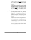
The output produces a negative pulse 80ms wide and supports speeds
from zero to 100 knots (clamps at 100kt).
200 ppnm
output