


TRANSFER BOX
DESCRIPTION AND OPERATION 11
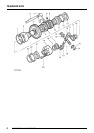
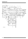
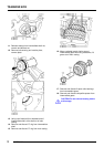
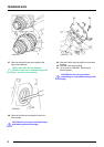
TRANSFER BOX CROSS SECTION
1. Main casing
2. Front output housing
3. Rear output housing
4. Dog clutch
5. Transmission brake
6. Mainshaft input gear
7. Selective shim - input gear bearing pre-load
8. Intermediate gear cluster
9. Intermediate shaft
10. Collapsible spacer
11. Differential assembly
12. Selective shim - differential bearing pre-load
13. Low range gear
14. High/low selector sleeve and hub
15. High range gear and bush
16. Differential rear bearing
17. Front output shaft
18. Differential lock selector shaft
19. Selector fork
20. Rear output shaft
DESCRIPTION
Introduction
The LT230T transfer box is mounted at the rear of
the main gearbox and transmits drive to the front
and rear axles via the propeller shafts.
Construction
The transfer box comprises three main assemblies,
the main casing, front output housing and rear
output housing.
The main casing carries the mainshaft input gear,
the intermediate gears and the differential together
with the high/low range gears, selector shaft and
fork.
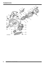
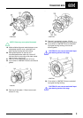
The front output housing carries the front output
shaft and flange, high/low cross shaft, housing and
selector and the differential lock selector shaft and
fork. A dog clutch on the front output shaft is
operated by the differential lock selector fork to
engage/disengage the differential lock.
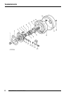
The rear output housing carries the rear output shaft
and flange and the speedometer drive and driven
gears. A mechanically operated transmission brake
is attached to the housing, the brake drum being
attached to the output flange.
All housings and cover plates are sealed to the the
main casing by gaskets or sealant; mud and water
ingress being prevented by mud shields and
throwers located at each end of the output housings
and on the drive flanges.
Mainshaft input gear
The gearbox output shaft is splined into the
mainshaft input gear which is supported by taper
roller bearings.
Input gear bearing pre-load is achieved by the use of
a selective shim located in the bearing housing. An
additional power take-off gear is located at the rear
of the input gear for certain applications.
Intermediate gears
The intermediate gear cluster is supported by taper
roller bearings located at each end of the cluster and
running on the intermediate shaft which, in turn, is
supported at the front and rear by the main casing.
Intermediate gear bearing pre-load is achieved by
means of a collapsible spacer positioned between
the bearings, the amount of compression applied to
the spacer is by means of a nut on the end of the
intermediate shaft.