


Page 6-8 G3X Installation Manual – Antennas
Revision A 190-01115-01
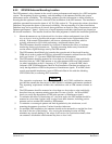
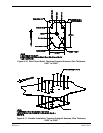
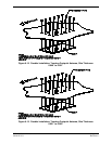
6.4.2 Antenna Installation Instructions
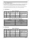
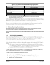
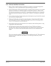
1. Refer to Table 6-5 and the drawings in Appendix C for guidance on selecting the appropriate
mounting cutout. Drill or punch the holes to match the mating part (doubler).
2. Install a doubler plate to reinforce the aircraft skin, as required. Refer to Section 6.4.1 for doubler
preparation and Table 6-5 for additional guidance on the doubler installation. Dimple aircraft
skin when the skin thickness is less than 0.051” for installation of flush head rivets. Countersink
aircraft skin when the skin thickness is between 0.051” and 0.063” for installation of flush head
rivets.
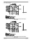
3. For the stud mount teardrop footprint antenna, place install gasket on top of aircraft skin using the
four screw holes to align the gasket.
4. Washers and locking nuts are required to secure the antenna. Torque the four #8-32 stainless
steel locking nuts 12-15 in-lbs. Torque should be applied evenly across all mounting studs or
screws to avoid deformation of the mounting area.
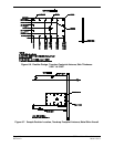
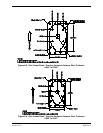
5. Ensure that the antenna base and aircraft skin are in continuous contact with the gasket or o-ring,
as appropriate to the antenna model.
6. Seal the antenna and gasket to the fuselage using Dow Corning 738 Electrical Sealant or
equivalent. Run a bead of the sealant along the edge of the antenna where it meets the exterior
aircraft skin. Use caution to ensure that the antenna connectors are not contaminated with
sealant.
CAUTION
Do not use construction grade RTV sealant or sealants containing acetic acid. These sealants may
damage the electrical connections to the antenna. Use of these type sealants may void the
antenna warranty.