


Page 1-2 G3X Installation Manual –Installation Overview
Revision A 190-01115-01
1.3 System Overview
The G3X is an advanced technology avionics suite designed to integrate pilot/aircraft interaction into one
central system. The system combines primary flight instrumentation, aircraft systems instrumentation,
and navigational information, all displayed on one, two, or three color screens. The G3X system is
composed of several sub-units or Line Replaceable Units (LRUs). LRUs have a modular design and can
be installed directly behind the instrument panel or in a separate avionics bay if desired. This design
greatly eases troubleshooting and maintenance of the G3X system. A failure or problem can be isolated
to a particular LRU, which can be replaced quickly and easily. Each LRU has a particular function, or set
of functions, that contributes to the system’s operation. For additional information on LRU functions, see
the applicable section of this manual.
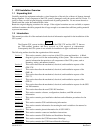
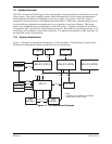
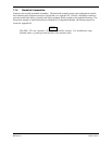
1.3.1 System Architecture
Figure 1-1 illustrates an example block diagram of a G3X installation. The flexibility of system allows
the installer to determine the architecture that best fits each installation.
CAN
GNS
430(W)
(1)
GSU 73
GDU 37X (PFD1)
GMU 44
GTP 59
RS-485
GTX 330
Autopilot
RS-232
RS-232
Pitot
Static
GNS
430(W)
(1)
SL 30/40
RS-232
A429 (GPS)
A429 (NAV)
RS-232
RS-232
Notes:
(1) Maximum of 2 COM/NAV units installed.
(2) GDU 37X to SL40 is TX only.
RS-232
ELT
RS-232
A429 (AIR DATA)
STEREO/MONO AUDIO
GMA 240
A429
Config Module
Config Module
A429 (GPS)
A429 (NAV)
GDU 37X (MFD)
GDU 37X (PFD2)
(1, 2)
RS-232
Figure 1-1. G3X Interconnect Example